
Bambu P2S - Smart Heated Chamber Mod 300W PTC
Print Profile(1)
Bill of Materials


Description
So you don't want to sell your P2S for an X2D, but you need chamber heating.
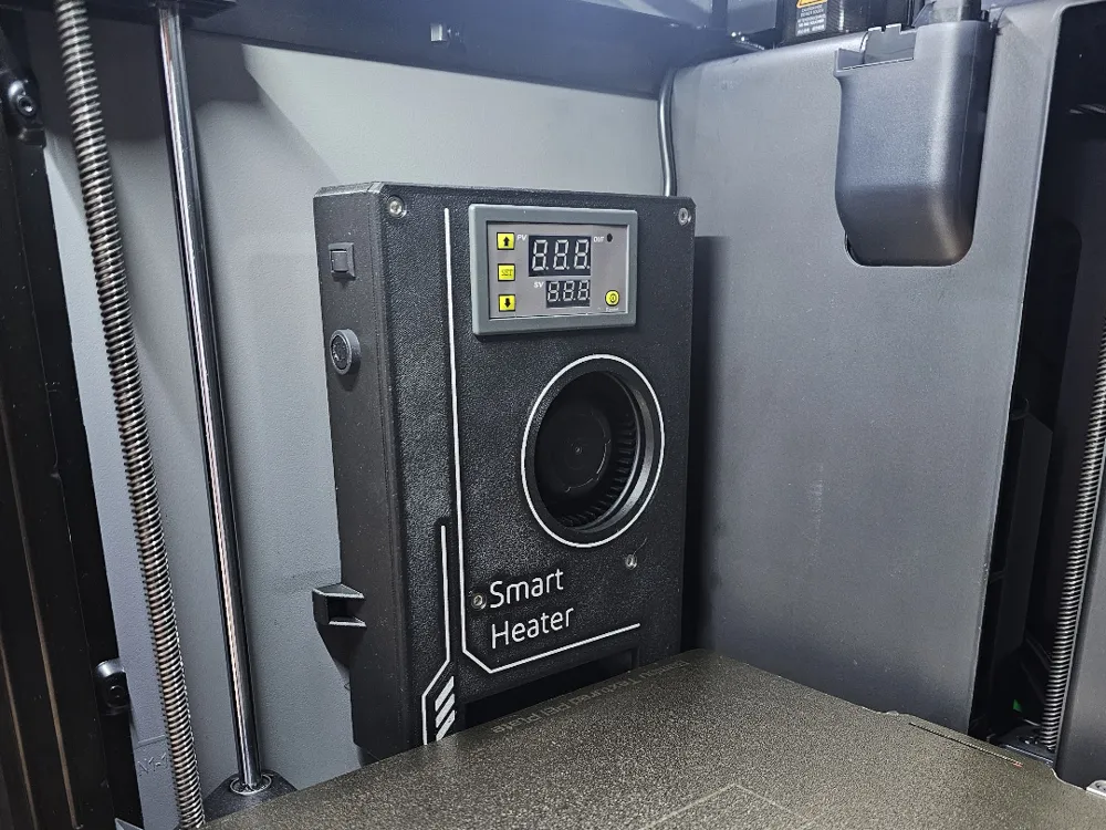
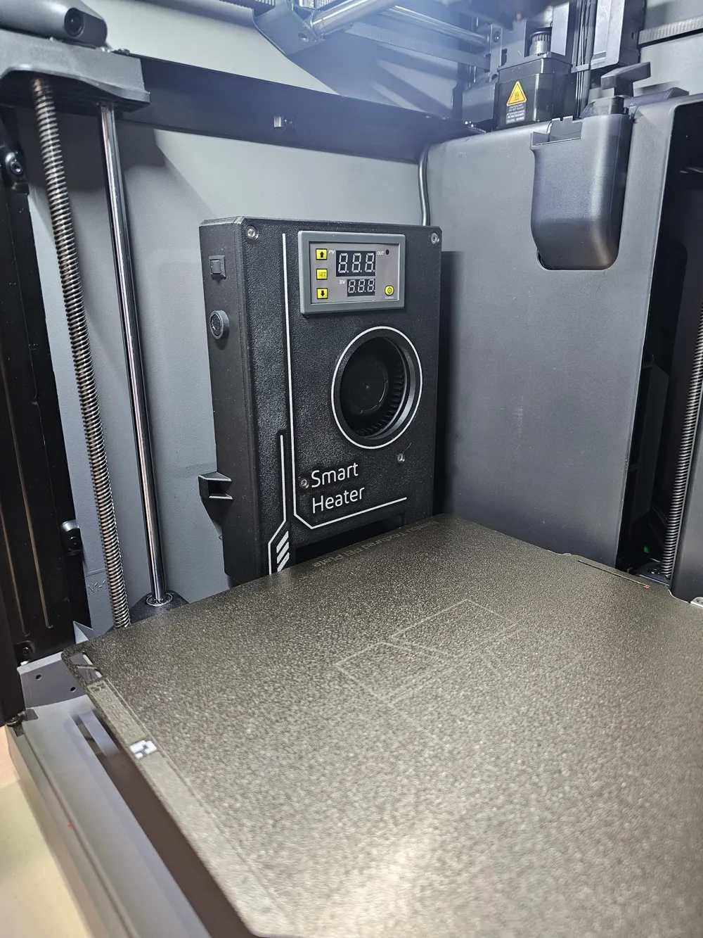
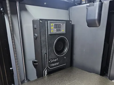
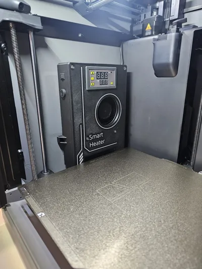
This project adds a fully automatic heated chamber system to the P2S using a dedicated PTC heater assembly, smart material detection, and motherboard cooling control. In my use case it turns on when the bed temperature set point > 90 degrees and turns off when the print is complete.
Check my github for the latest firmware: https://github.com/AW-I/BBL-Smart-Heater
The system is split into 3 main parts:
Stage 1 — Chamber Heater Unit
The chamber heater is a pure 240V implementation with the following features:
- Adjustable temperature via display panel
- Mounts using factory holes
- Fused for safety
- Dedicated power switch
- Over temperature thermostat on both the PTC and case (85C)
This can be used standalone, you can just manually turn it on at the start of a print and off when the print is finished.
Stage 2 — ESP8266 Smart Controller (Optional)
The second part of the project is an ESP8266-based Relay controller, it connects to WiFi and the printers MQTT topic it does the following:
- Enables chamber heating when bed temperature set point ≥ 90C
- Disables heating bed temperature set point is set to 0 (print finished)
- Shuts the heater off if the chamber gets too hot
- PWM fan support
This gives most of the functionality as the X2D in my eyes, it also doesn't require LAN mode to be active.
Stage 3 — Motherboard Cooling System (Optional)
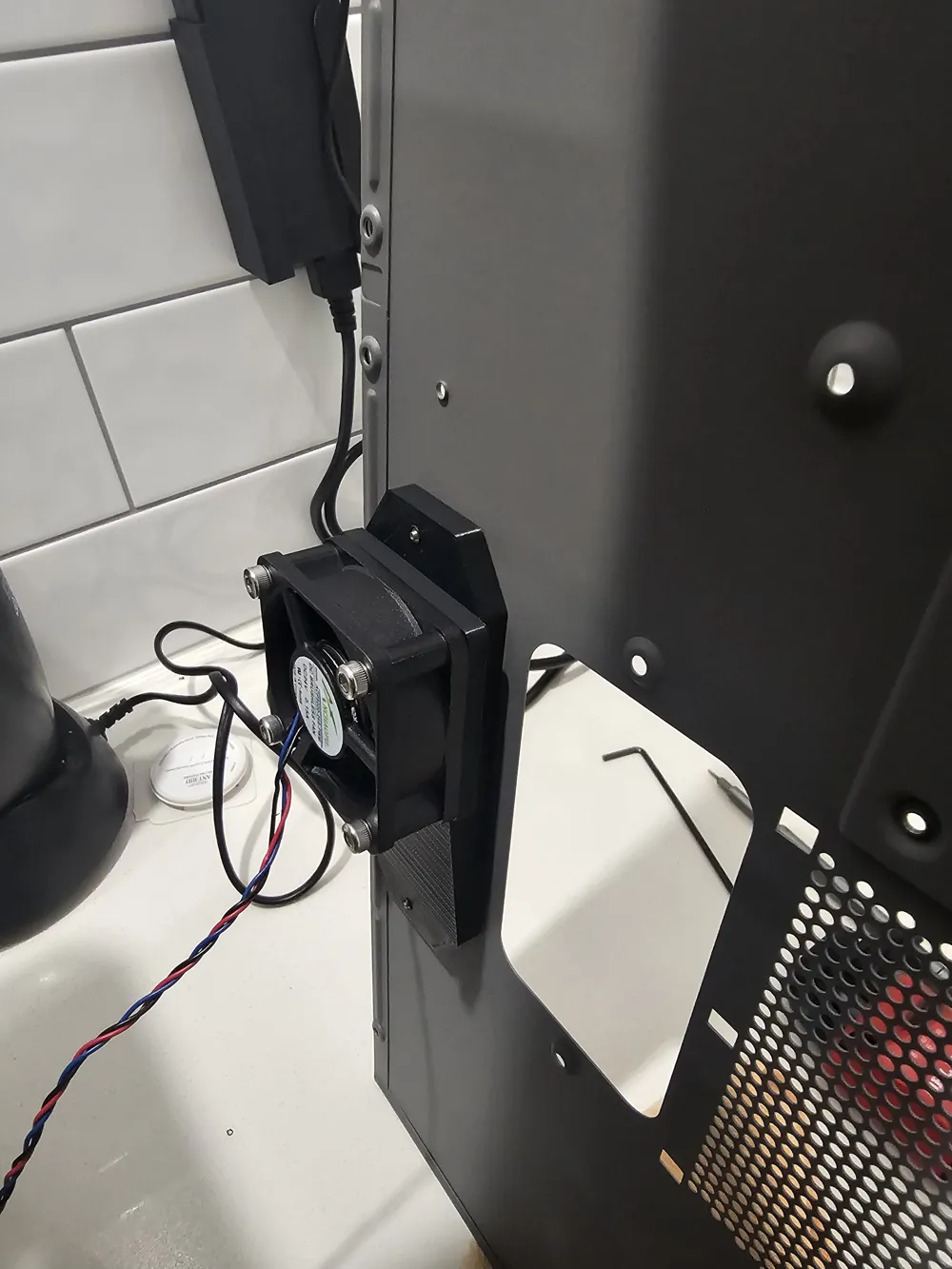
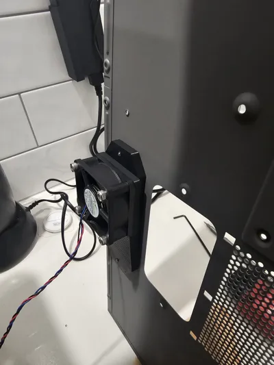
Because the motherboard heat sink is mounted to the frame of the printer I added a PWM cooling fan to cool the components:
- Configurable via the smart controller
- Default settings turns it on when the chamber hits 65C.
Bill of Materials (BOM)
Stage 1 — Heater Assembly
Main Components
| Item | Link | Qty |
|---|---|---|
| PTC Heater (220V 300W) | https://www.aliexpress.com/item/32697806892.html | 1 |
| Blower Fan (220V) | https://www.aliexpress.com/item/1005002734612429.html | 1 |
| Thermostat (70 Degree NC) | https://www.aliexpress.com/item/33042938040.html | 1 |
| Fuse with mount (3A) | https://www.aliexpress.com/item/1005005962742112.html | 1 |
| Rocker Switch (3A) | https://www.aliexpress.com/item/4000973563250.html | 1 |
| Temperature Controller ( 220V ) | https://www.aliexpress.com/item/1005008051389866.html | 1 |
| Higher temp thermostat for PTC (85C NC 5A) | https://www.aliexpress.com/item/1005009052433219.html | 1 |
Assembly Hardware
| Item | Description | Qty |
|---|---|---|
| M4 x 6mm Bolt | Used to attach lid to body (6) | 6 |
| M4 x 35mm Bolt | Fan to body (2) | 2 |
| M4 x 5mm OD x L4mm heat set | Lid to body (6) & Fan to body(2) | 8 |
| M3 x 16mm Bolt | Cable Strain Relief (2) | 2 |
| M3 x 4mm Bolt | Thermostat to body (2) | 2 |
| M3 x 5mm OD x L4mm heat set | Cable Strain Relief to Body (2) & Thermostat to body (2) | 4 |
Stage 2 — ESP8266 Controller
| Item | Description | Qty |
|---|---|---|
| ESP8266 Relay Board | https://www.aliexpress.com/item/1005010435047645.html | 1 |
| M4 x 6mm Bolt | Main bracket to printer (2) | 2 |
| M4 x 5 OD x L4 heat set | Main bracket to printer (2) | 2 |
| M2 x 4mm Bolt | Lid to Case (4) & PCB to Case (2) | 6 |
| M2 x 3.2mm OD x L3 Heat set | Lid to Case (4) & PCB to Case (2) | 6 |
Stage 3 — Cooling System
| Item | Description | Qty |
|---|---|---|
| 24V 5010 PWM Fan | https://www.aliexpress.com/item/1005010590135806.html | 1 |
| M4 x 25mm Bolt | Fan to bracket (4) | 4 |
| M4 x 5mm OD x L4mm heat set | Fan to bracket (4) | 4 |
| M2 x 6mm Bolt | Bracket to printer back plate (2) | 2 |
| M2 x 3.2mm OD x L3 Heat set | Bracket to printer back plate (2) | 2 |
Assembly Instructions
Step 1 — Printed Parts
- Print all required components using a heat resistant material (ASA/ABS/Nylon/PC)
- Insert all required heat sets.
Step 2 — Assemble the Heater Unit
Note if you need the chamber heater to exceed 50C you will need to swap the thermostat on the PTC with an 85C thermostat (link is in the BOM). The included 70C thermostat hysteresis resets at 50C so the heater stops heating till it returns to 50C.
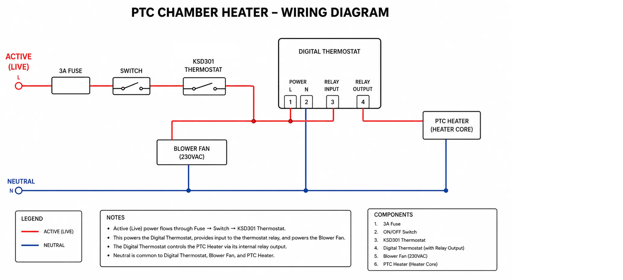
- Use the following wiring diagram for wiring the unit.
2. Ensure all connections are tight by pulling on them firmly and protected against short circuits. Don't forget to route the temperature sensor.
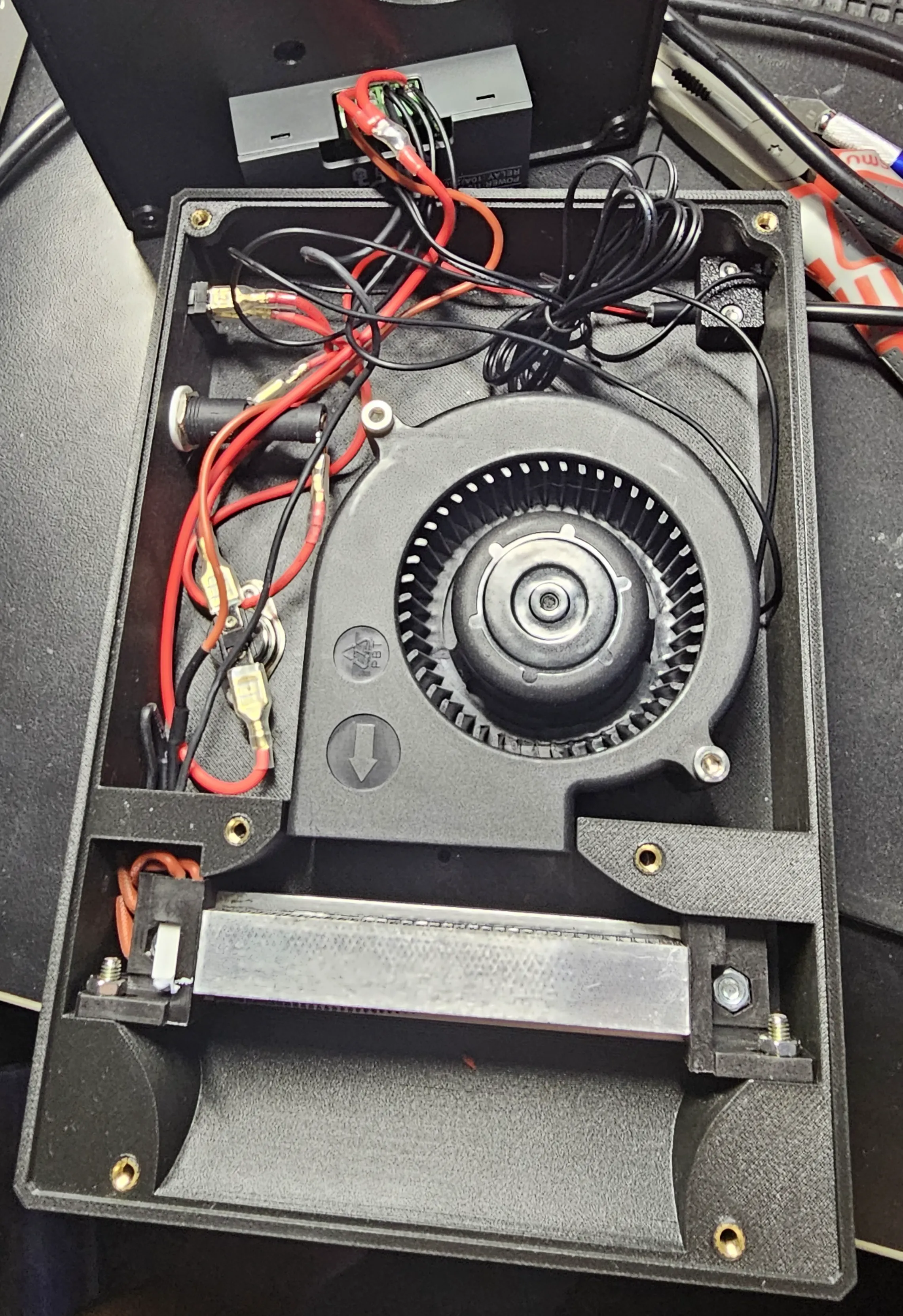
3. Do a bench test, remember this is mains power do not touch anything while operating or plugged in.
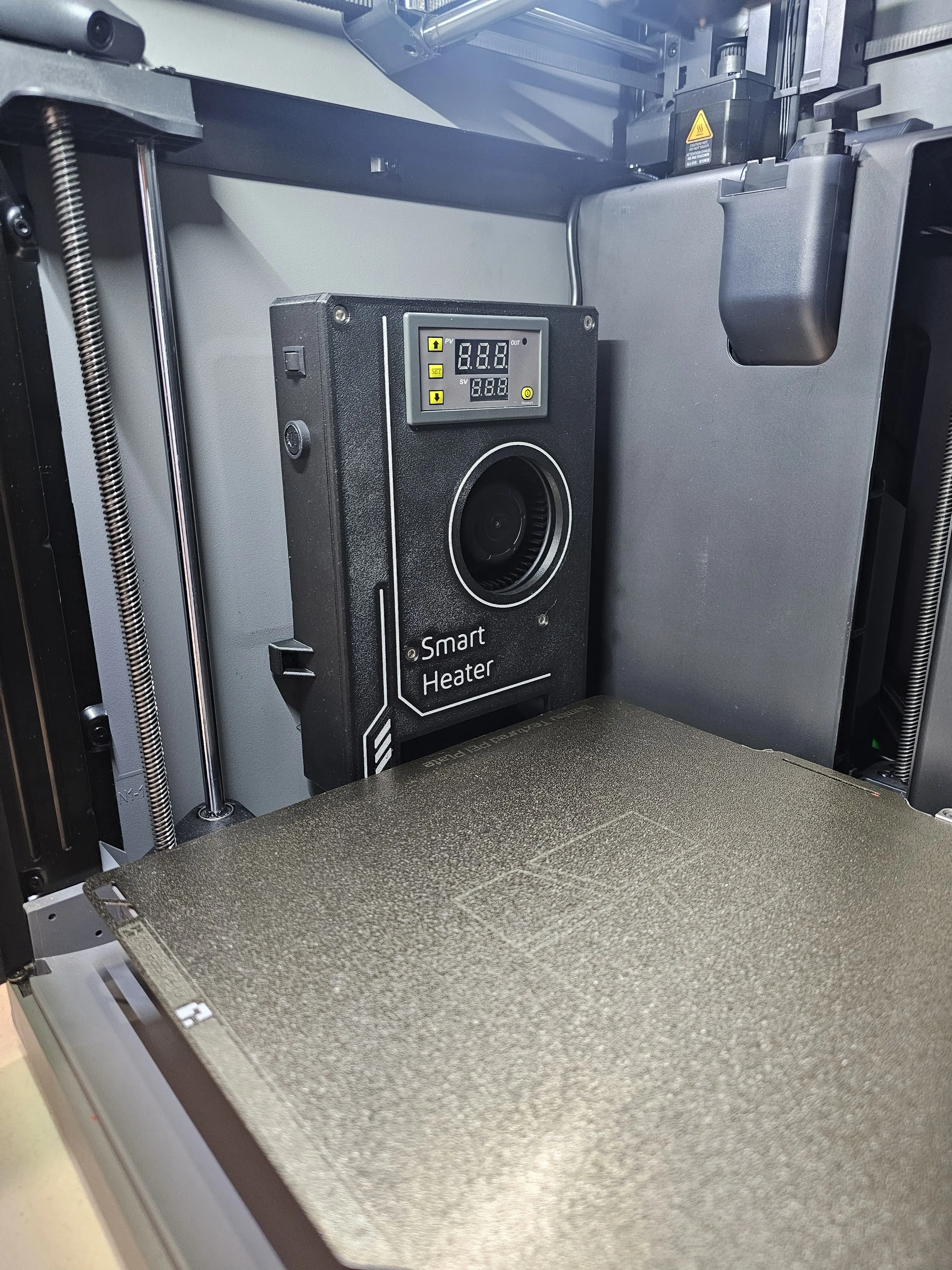
Step 3 — Mount the Heater Unit
- Use double sided tape to stick heater to side panel.
- Use BT3-6 x 3 Screws into side panel to add extra strength (Need to remove front cover of heater to access screw holes)
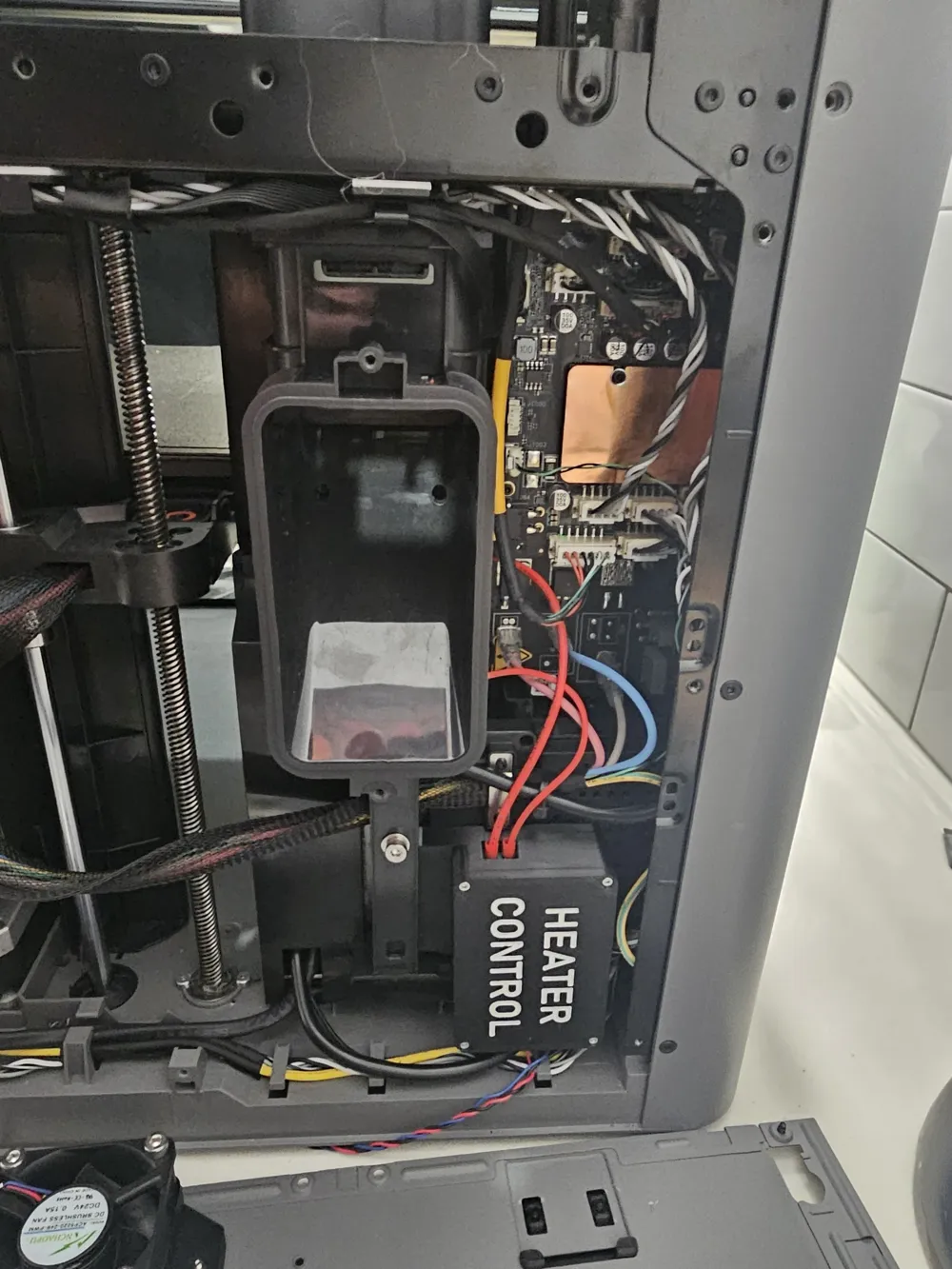
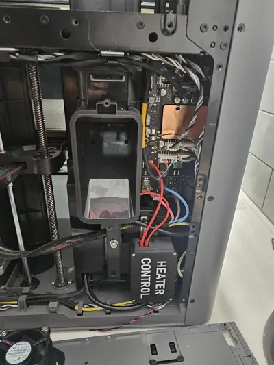
- Run wiring through to back ( there is a gap on the left side near the stepper motor)
- Remove back panel for wiring (https://wiki.bambulab.com/en/p2s/maintenance/replace-rear-panel)
- Remove Purge Chute (https://wiki.bambulab.com/en/p2s/maintenance/replace-mc-and-ac-boards)
- Remove Power cover (https://wiki.bambulab.com/en/p2s/maintenance/replace-mc-and-ac-boards)
- If you are not installing the smart controller simply connect up the active and neutral and use the switch to activate.
Step 4 — Install the ESP8266 Controller
Download the Arduino IDE and install the ESP8266 core (https://github.com/esp8266/arduino)
Download the source (https://github.com/AW-I/BBL-Smart-Heater)
- Flash the controller using the Arduino IDE & a RS232 to USB adapter( Short the boot pins and power cycle the unit to enter programming mode)
- Install the board in the enclosure, there's only one correct orientation ( relay facing the sky )
Connect wires(It's tight but can be done)
- Connect 24V & GND from the PSU (Use downward exit)
- Connect heater neutral to share heated bed connection
- Connect active from heated bed connection to relay in
- Connect relay out to heater active
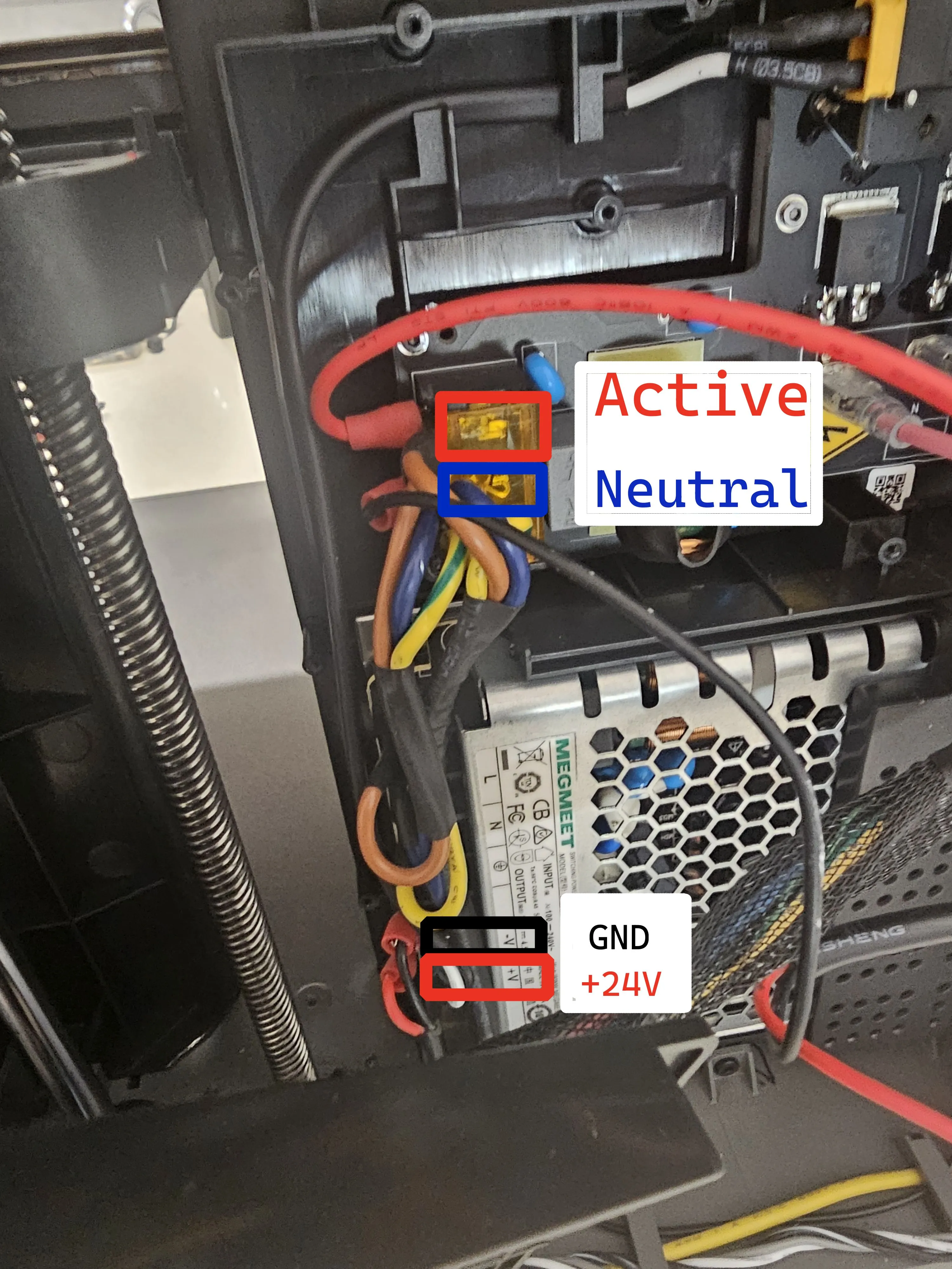
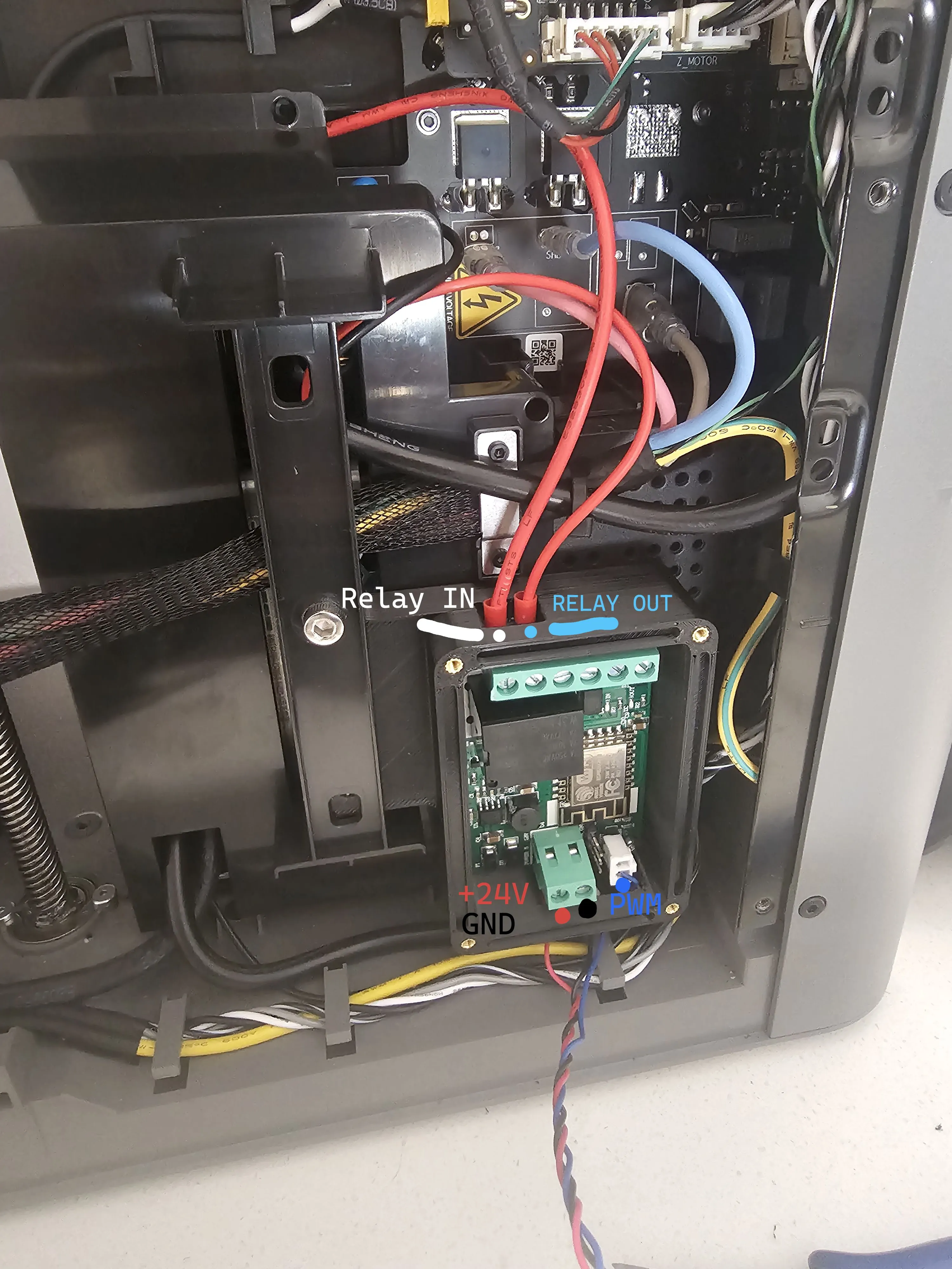
Finally mount the enclosure and secure the lid in place.
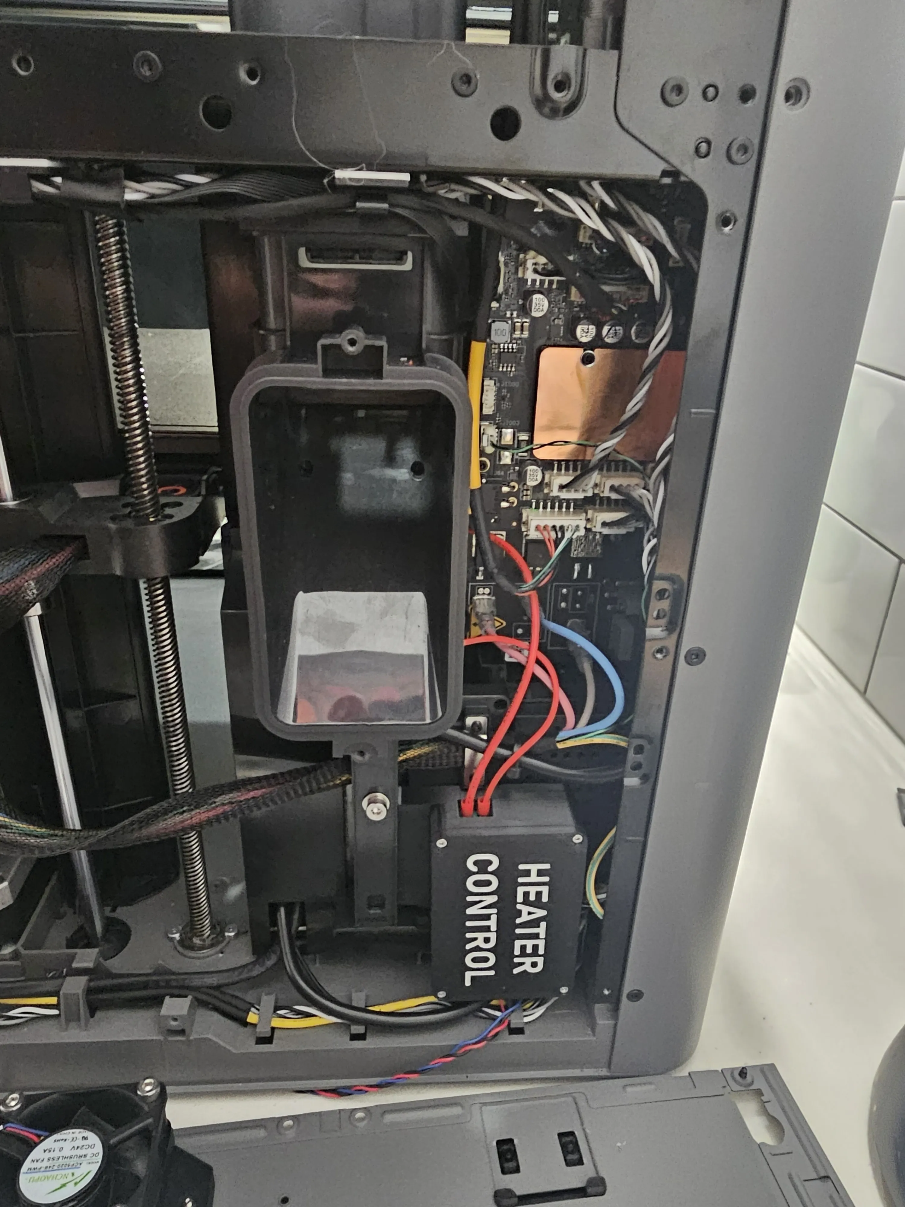
Step 5 — Install Motherboard Cooling
- Install the Fan onto the mounting bracket in the intake position (blowing air in).
- Cut the plug off and remove yellow wire (tachometer input)
- Wire 24V & GND to share the ESP8266 Controller power
- Wire the blue wire (PWM) to the boot pin on the ESP826 Controller
- Mount the fan & go in reverse order to put back together.
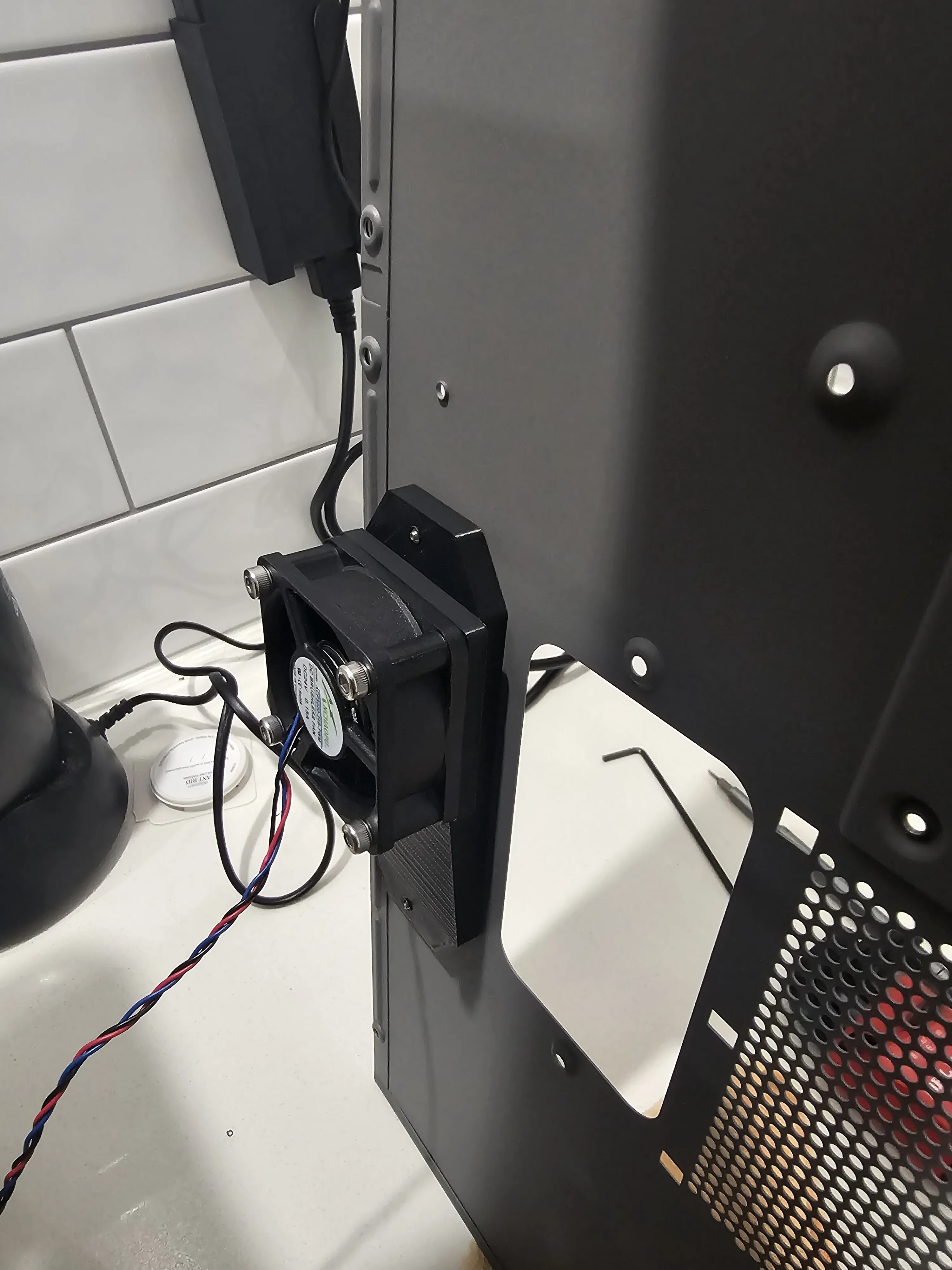
Important Safety Information
⚠️ This project uses mains voltage (240V AC).
⚠️ Incorrect wiring can cause electric shock, fire, or equipment damage.
⚠️ Use appropriately rated wiring, insulation, connectors, and fusing.
⚠️ I am not responsible for anything that goes wrong.
⚠️ Verify temperatures around electronics and printed components during initial testing.
⚠️ I've done my best to document everything but I may have missed some steps.
License

You shall not share, sub-license, sell, rent, host, transfer, or distribute in any way the digital or 3D printed versions of this object, nor any other derivative work of this object in its digital or physical format (including - but not limited to - remixes of this object, and hosting on other digital platforms). The objects may not be used without permission in any way whatsoever in which you charge money, or collect fees.


Comment & Rating (0)