
The Freight Transfer Depot - HO-Scale Edition
Print Profile(2)


Description
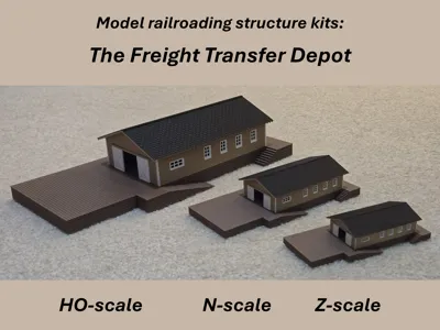
This model is the HO-scale version of the second in a series of “Thinline Scale Model” structure kits for Z-scale and N-scale model railroading. The Z-scale and N-scale kits are available here: https://makerworld.com/en/models/2705528-freight-transfer-depot-tsm-02-for-z-n-scale#profileId-2999119.
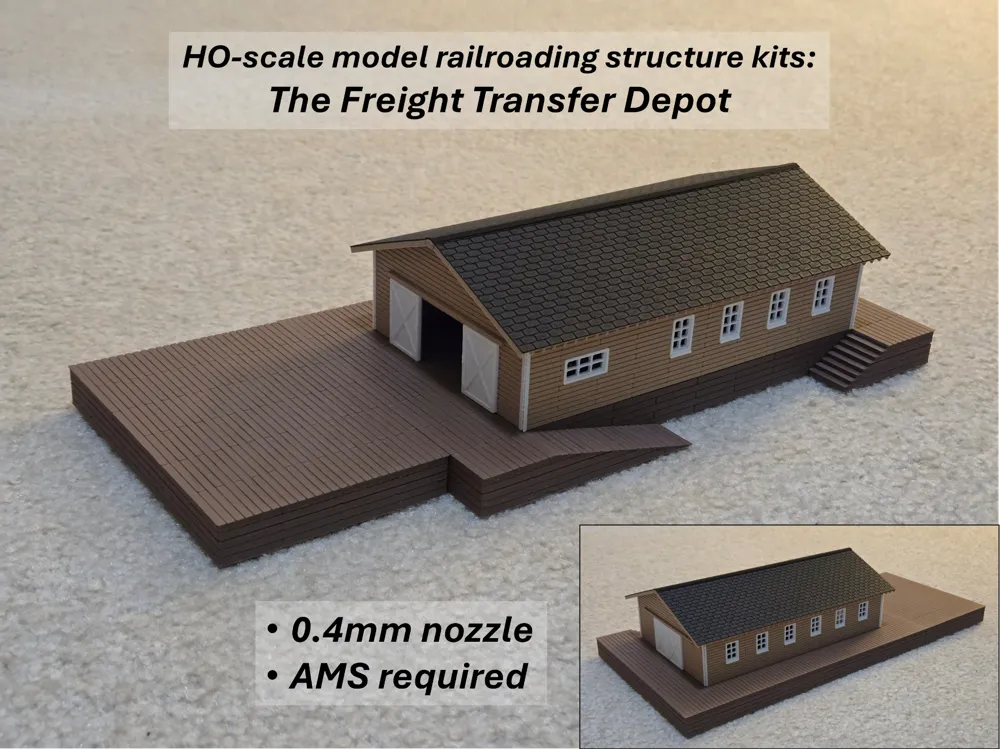
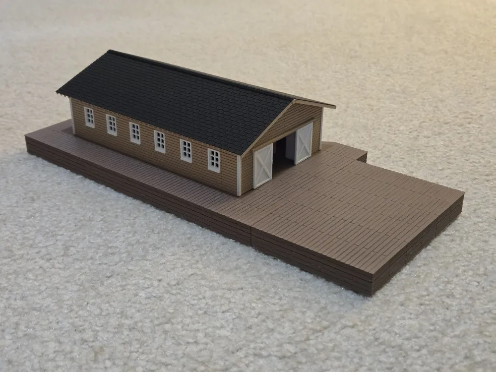
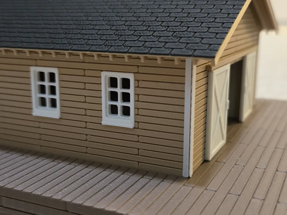
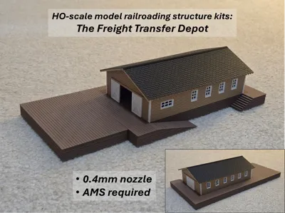
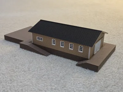
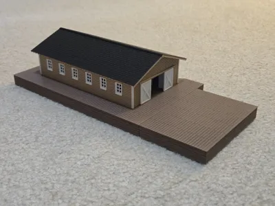
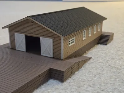
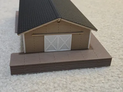
The Freight Transfer Depot (TSM#02-HO) - This structure kit is for a depot that might be seen along a train siding for transferring freight between trains and/or between trains and trucks.
Important Note: Before proceeding to print and build this kit, please note the following requirements needed to produce good results. Also, please read through the entire description to understand all of the assembly steps required.
- For printing, a 0.4mm nozzle and a clean smooth build plate is required - this model profile specifically uses a 0.20mm layer layer height given that its a scaled design from the Z-scale model which requires a 0.2mm nozzle and a 0.08mm layer height (0.08 x 220/87 = 0.20229 rounds to 0.20).
- This kit includes both two-color and three-color prints - an AMS is required.
- Supplied needed: fast setting (5-10 seconds) CA adhesive; and a selection of acrylic paints / brushes for painting the model (if desired).
- Tools needed: a good bed scraper tool for removing PLA prints from the smooth build plate - I found the bed scraping blade supplied with the printers by Bambu Lab to work well for this purpose (most beneficial was its thin sharp blade for lifting very thin prints).
The Print Profiles - Two profiles are available for this structure kit, the profiles differ by single (P1S, A1, H2S, etc.) and dual-nozzle (H2D, H2C, etc.) printers. Please note that all of the profiles include a number of parameter changes from the standard print profiles that probably should not be tampered with if you want good results. One of the more important profile variances is that I've significantly slowed down the nozzle speed, travel speed and acceleration to help assure the best result printing the detail features of these models - I've specifically supplied separate profiles based on direct-drive nozzle count because changing the printer of a single-nozzle profile to a dual-nozzle printer (and vice versa) may cause the nozzle-specific speed settings to be lost in the profile. I highly recommend that you use the appropriate single or dual-nozzle profile matching your printer capability.
Note: While I included the X2D with the dual-nozzle printers, you may choose to treat it as a single-nozzle printer (e.g., use the A1 profile) given the fine details on sections of this model.
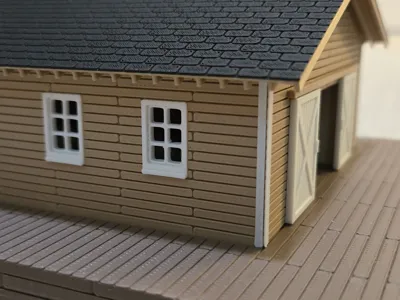
Choosing Filaments - In my profiles, I've chosen to use Bambu Lab PLA Matte filaments as I prefer the surface finish over PLA Basic. I've printed the walls and roof underlay Matte Latte Brown, and the window frames and doors in Matte Ivory White. The base is Matte Dark Brown and the roof asphalt shingling is Matte Charcoal.
Assembly Instructions
Before starting … you might want to consider painting options and window glazing.
At a minimum, I would suggest adding some diluted color washes to give a more weathered look to the structure. If you choose to change the filament colors to either reduce the number of filaments or simply to picking more neutral colors with a plan of painting the model, you should consider painting individual parts prior to assembly although adding weathering detail is often done with the overall model built up. Using some paint color washes can help enhance the details while also making the building not appear as it was just build yesterday :-).
If you want to add window glazing (simulated window glass), I would suggest that being done either before attaching the walls to the base, or at least right after attaching the walls to the base - going beyond those steps in the assembly process may make it difficult to add glazing. You also need to consider that if you are painting the model, care must be taken to not get paint on your window glazing so the painting versus glazing order become important.
Important note before removing the parts from the build plate: After printing your model, please only remove the parts after the build plate has completely cooled to room temperature. Some of the parts can't be removed simply by flexing the build plate, so with the build plate removed from the printer and set firmly on a work surface, use a sharp bed scraper tool to very carefully work up and lift each individual part by working slowly around the edges of the part.
Please take care to assure that when parts are being glued together, that all mating edges/surfaces are held in alignment so that there are no noticeable gaps in the assembly.
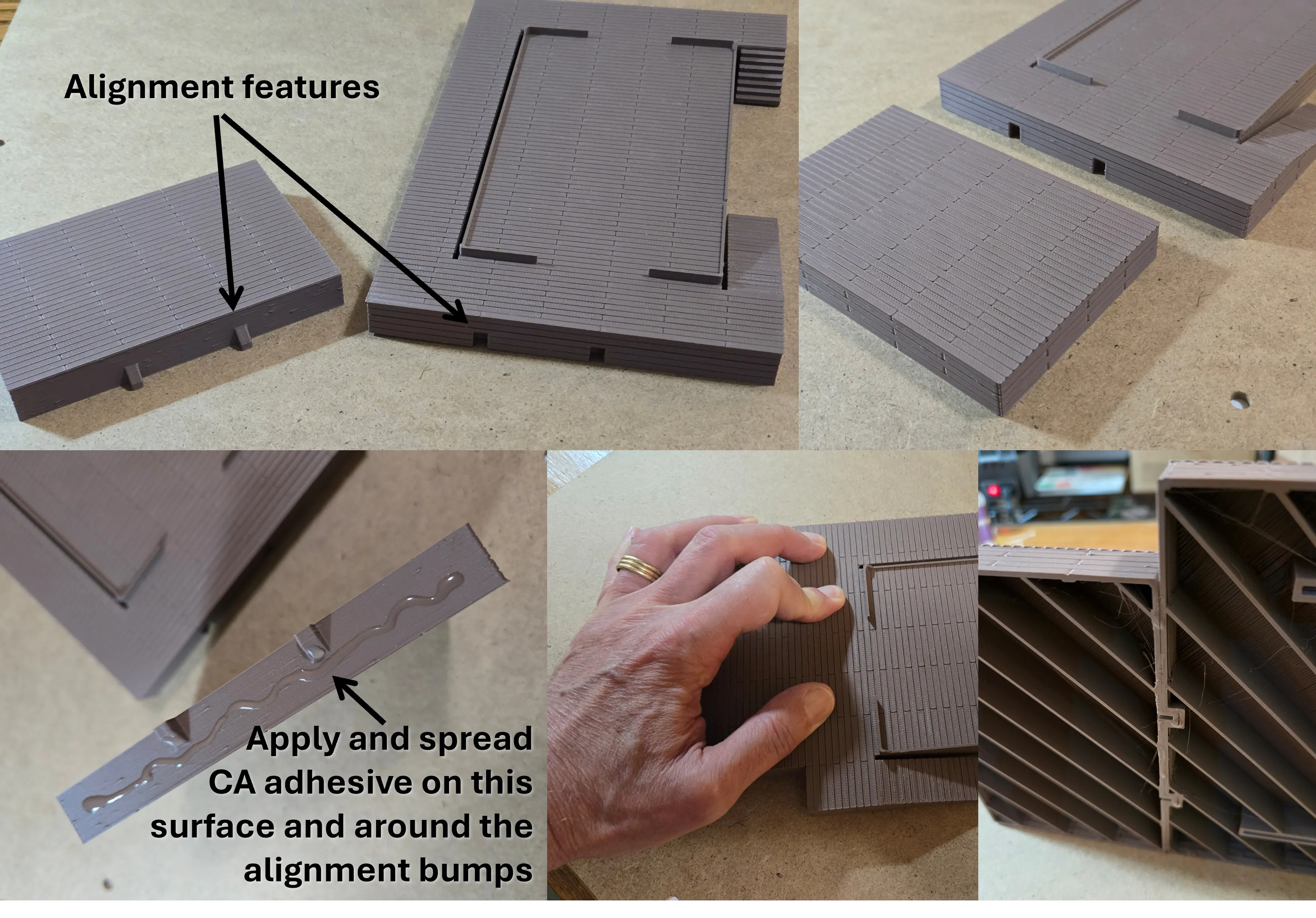
Step A - If the Base (1) was printed in two parts, align the front and back base pieces using the alignment features at the mating edge of each part. Given the size of the base, a generous amount of glue is required to cover the mating surface between the base parts, and be sure to get glue over/around the alignment bumps. For H2-series prints, the base is printed as a single piece.
Important for proper alignment during gluing: Make sure to place both parts of the base on a solid flat surface and press them together tightly while assuring the all of the edge line up nicely. While holding the parts together, I waiting somewhat longer than the normal setting time out of caution, and after I even added some additional CA along the seam on the underside of the base - I was probably a bit messier here than I should have been but I thought it important to make sure that the CA got well into the gap between the parts.
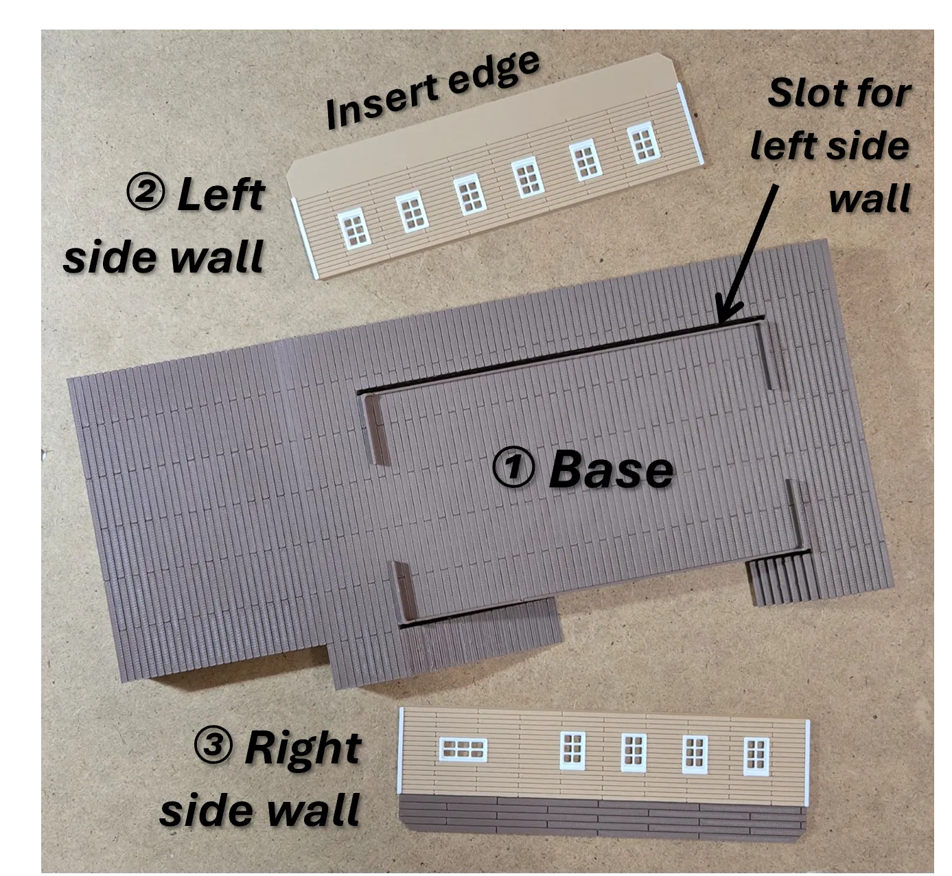
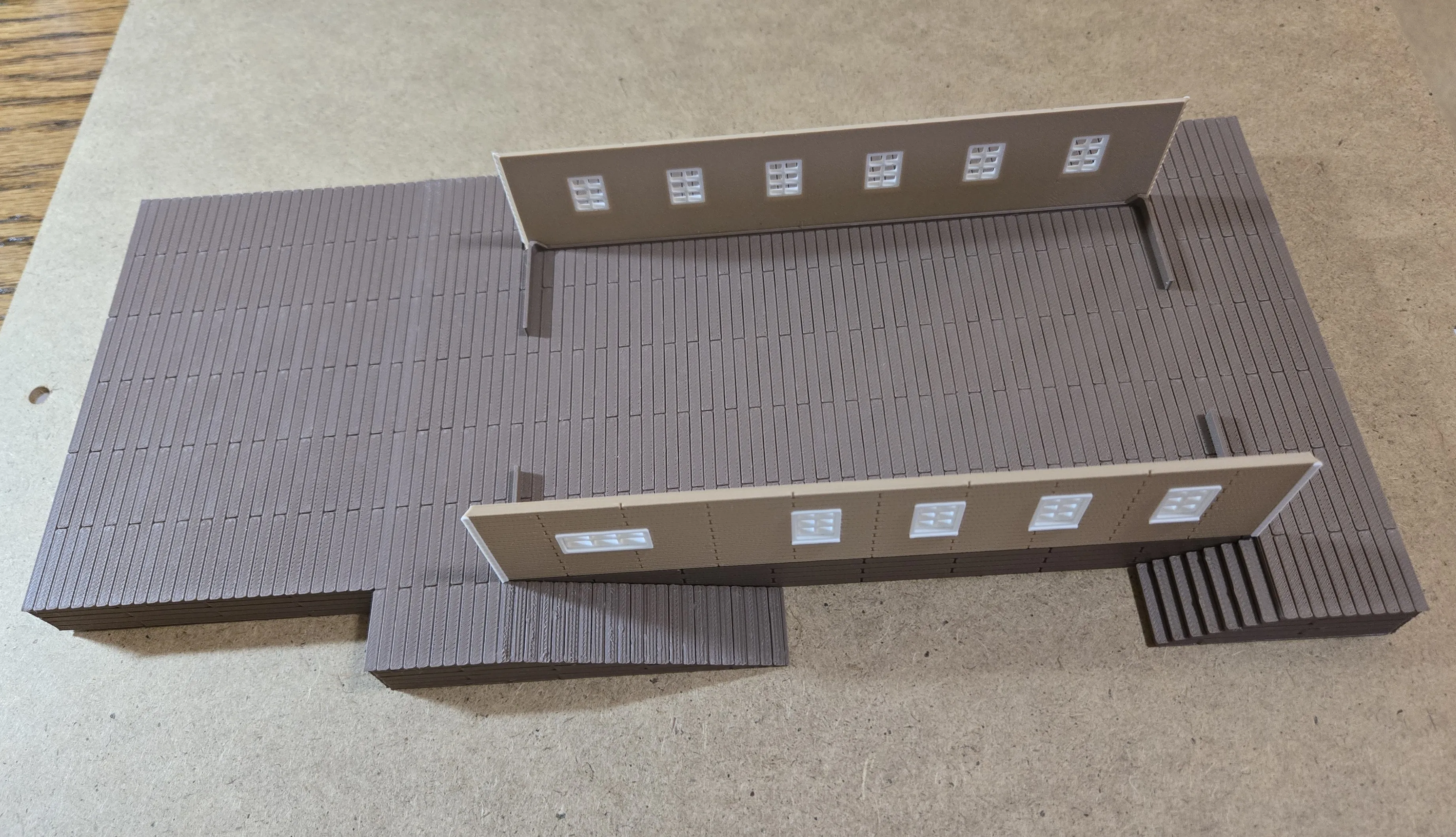
Step B - align the Left Side Wall (2) with its bottom edge positioned to insert in the left wall slot of the Base (1). Make sure to have the finished surface facing out and take care to press the lower part of the wall fully into the slot - its best to have the base firmly placed on your work surface such that when the wall is fully inserted it will align with the bottom of the base slot. The slot is intentionally sized to be a tight fit with the wall being inserted - take some care when inserting the left wall so as to not damage the slot edges.
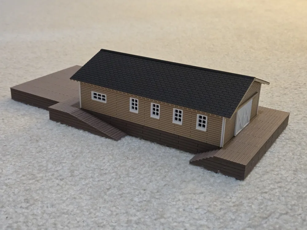
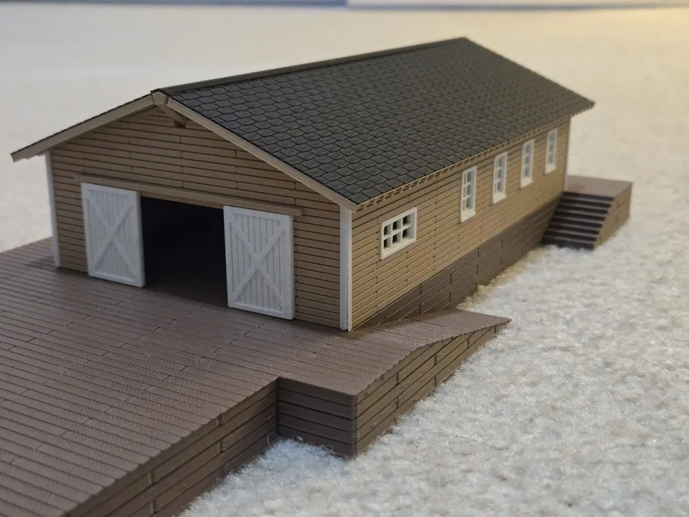
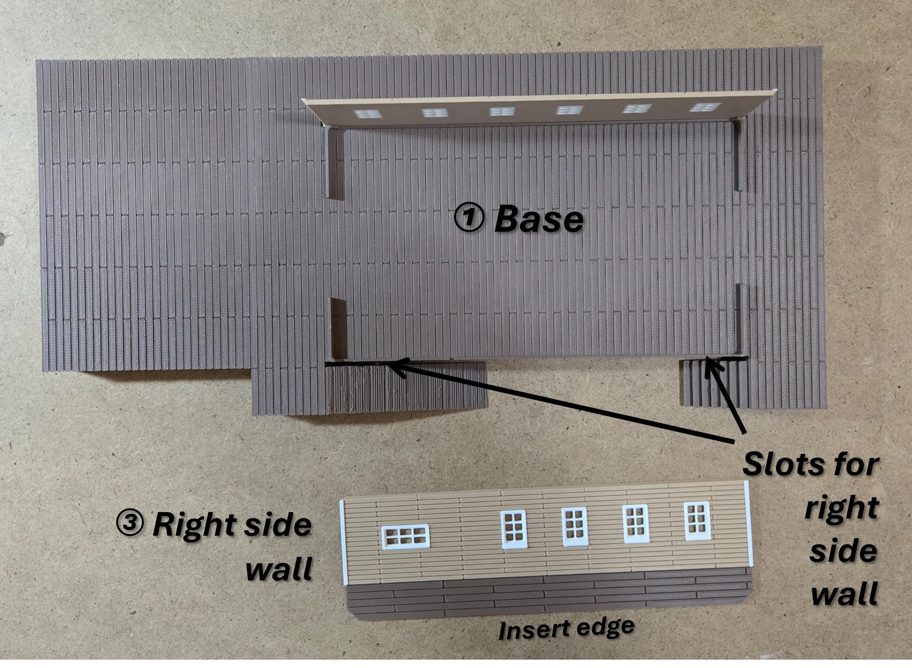
Step C - align the Right Side Wall (3) with its bottom edge positioned to insert in the right wall slots of the Base (1) - these ‘slots’ are the gaps between the ramp and stairs with the base. Again, make sure to have the finished surface facing out and take care to press the lower part of the wall fully into the slots. Again, the slots are meant to be a tight fit with the right wall but this time it should be a bit easier to insert - take some care to not damage either the ramp or stairs when inserting the wall.
Note: There should be no need to apply any glue to hold either the left or right side walls once in place. That said, if you find that the walls might be easy to pull out, feel free to apply some glue along the under side of the base where you can see the exposed bottom edges of the walls.
Step D - attach one of the Front/Back Walls (4) to the front of the structure using glue. Before adding glue, make sure to test fit everything and take note of how the front wall edges overlap each of the side walls. When applying the glue, please try to keep the drops relatively small (one of mine in this pic was a bit bigger than it needed to be :-) and for the sides the drops should be positioned right on the inside edge of the wall to try to keep it from seeping beyond the white outside corner. When attaching the wall with glue, take care to get it held in place nicely along each side edge and down flush with the base floor - you are striving to minimize the gaps at the outside corners where the walls meet.
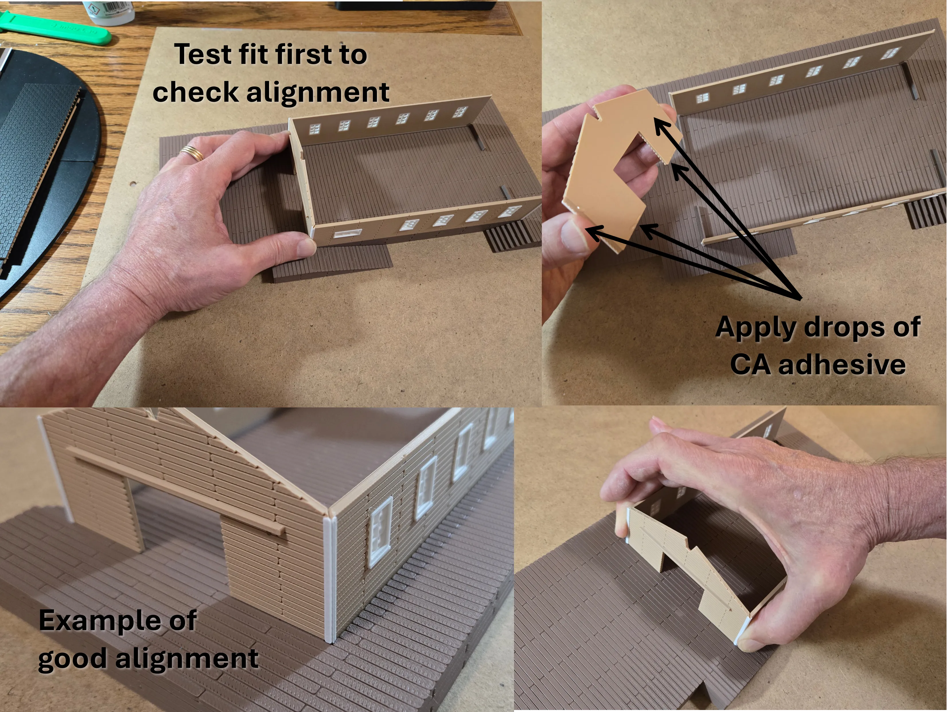
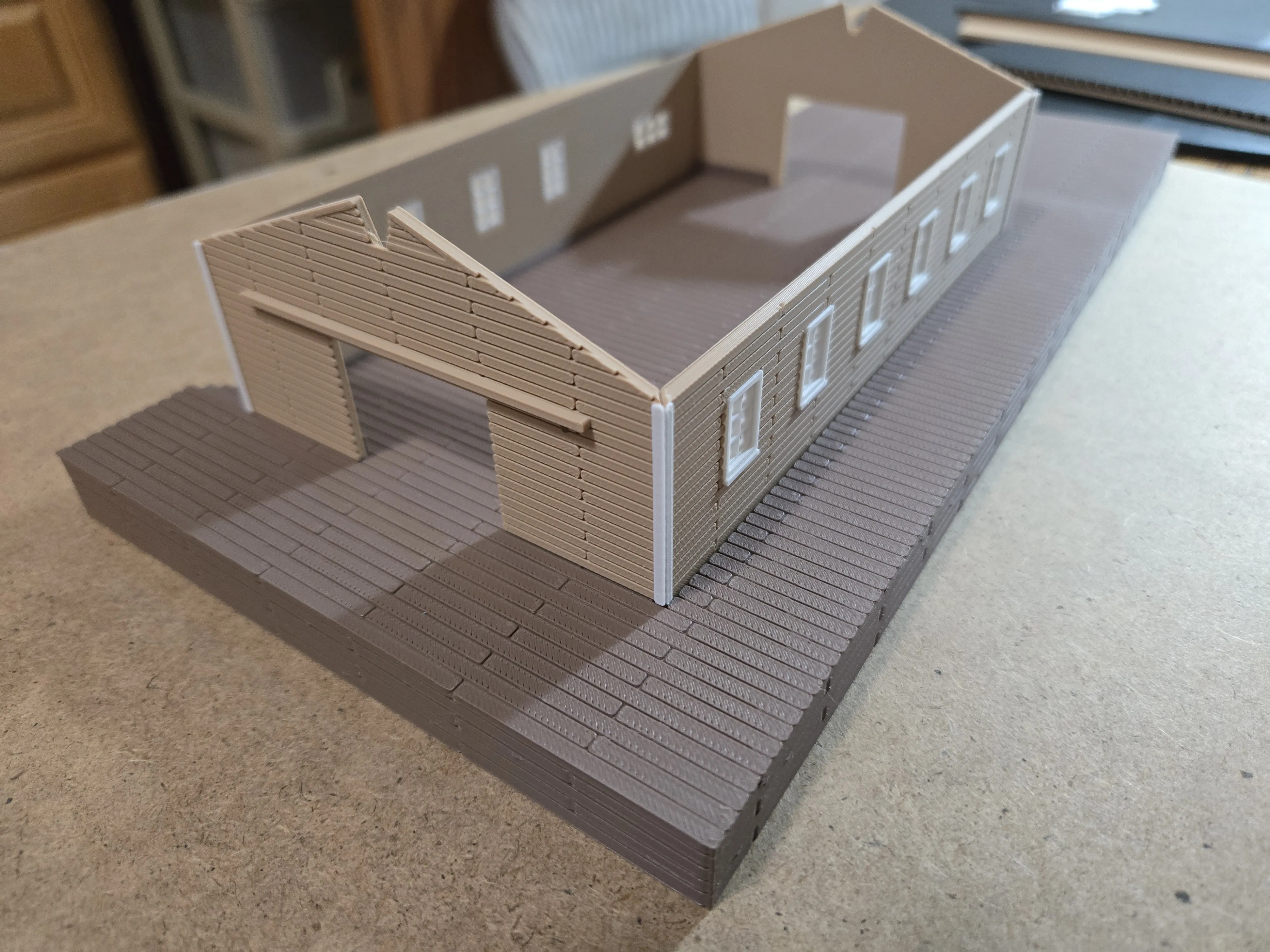
Step E - attach the remaining Back Wall (4) to the back of the structure using glue. Again, make sure to test fit everything and take note of how the back wall edges overlap each of the side walls before applying glue and attaching the wall.
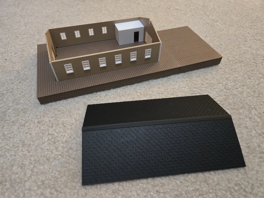
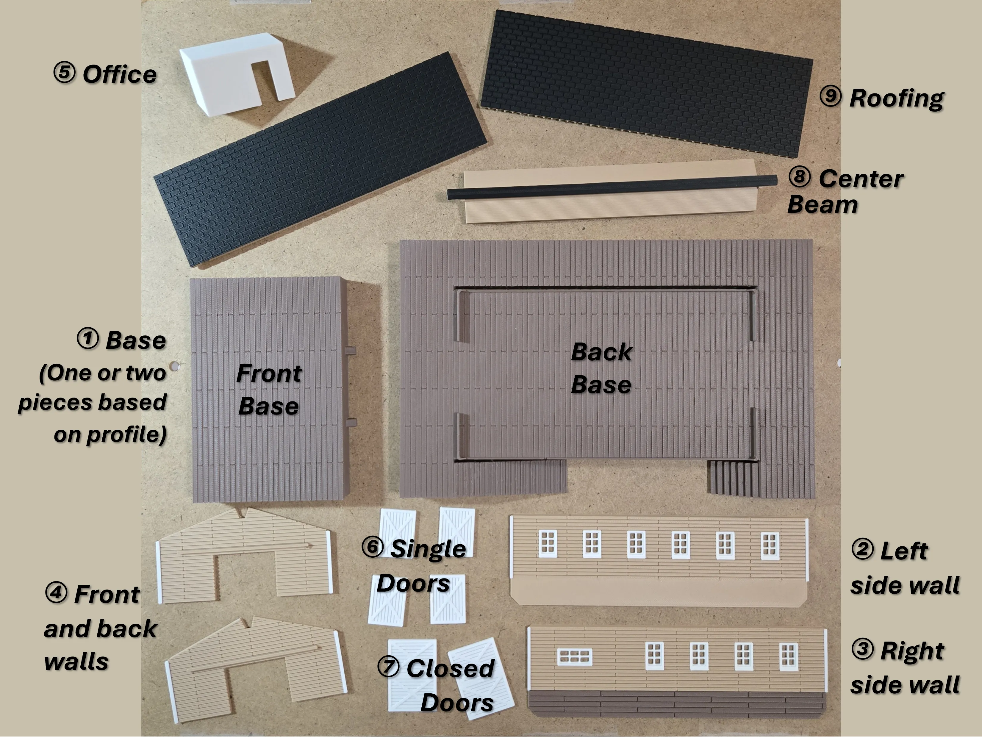
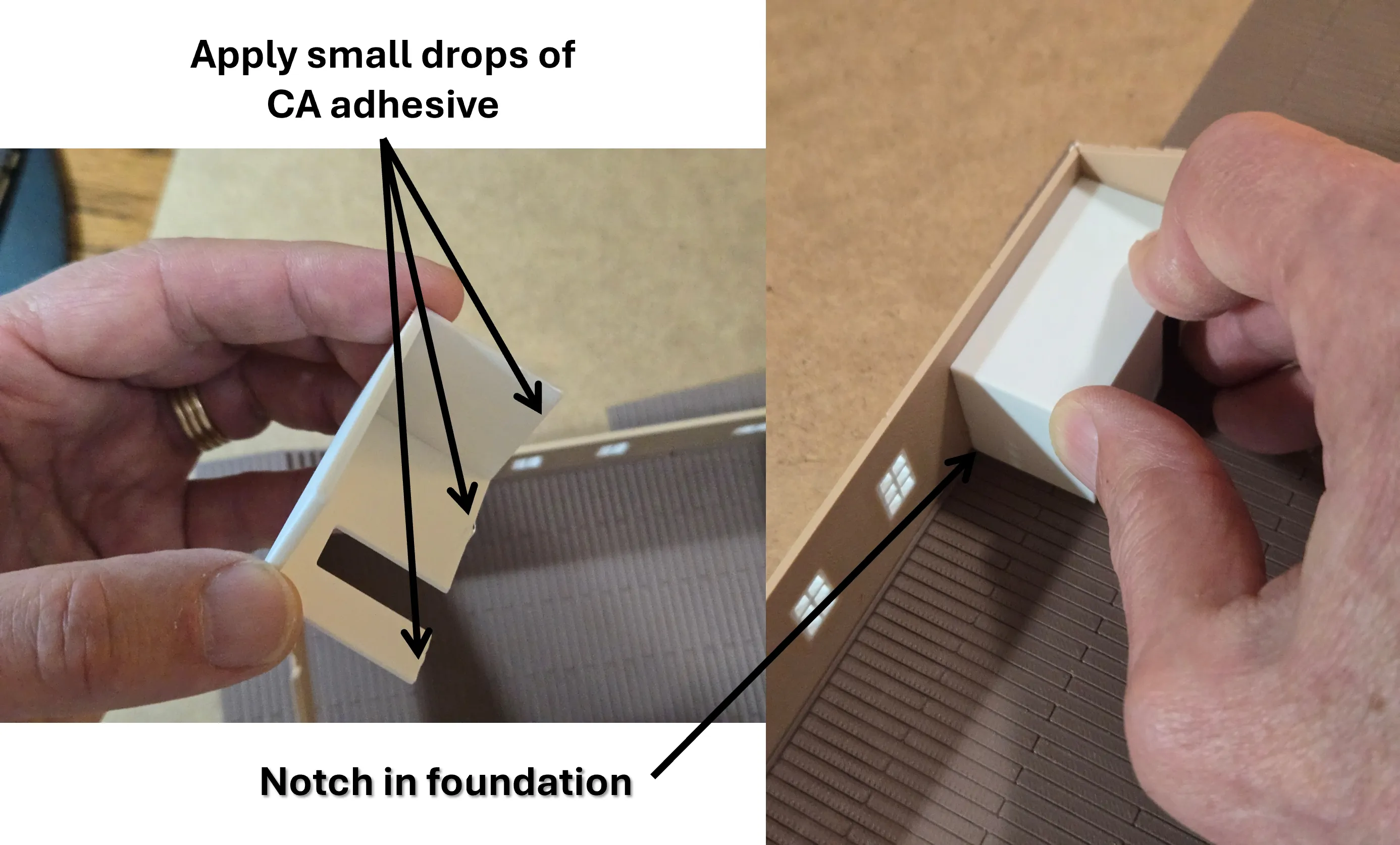
Step F - attach the inside Office (5) using glue. Before adding glue, test fit the office into the front right corner of the interior - note that there is a small notch in the foundation at the base of the Right Side Wall (3) where the office back wall can slide up tight to the right wall. The office is used to help visually isolate the horizontal window of the right wall which might be important if you ever intend to add interior lighting to this model.
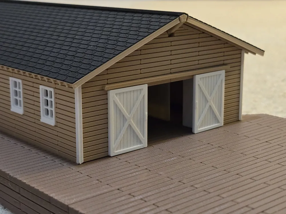
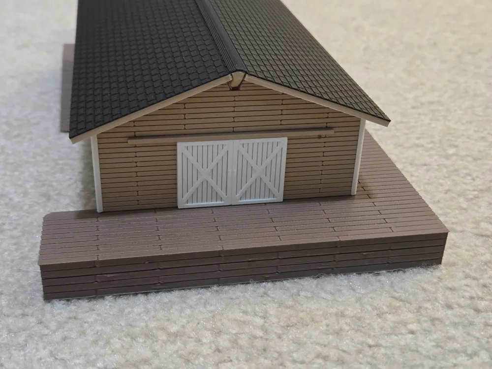
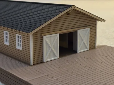
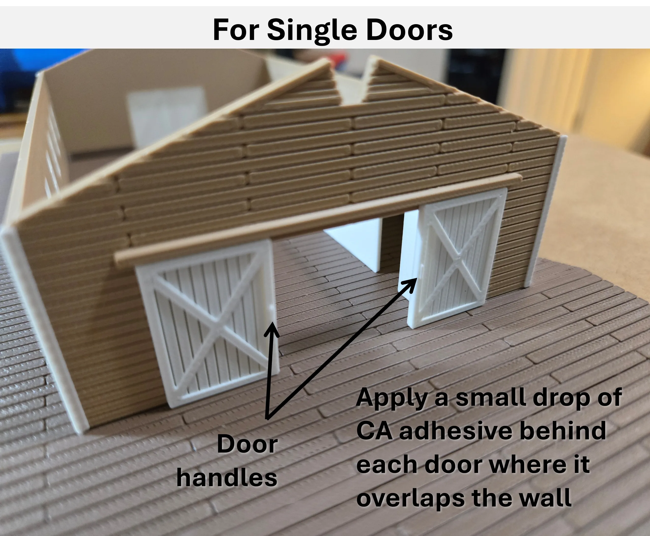
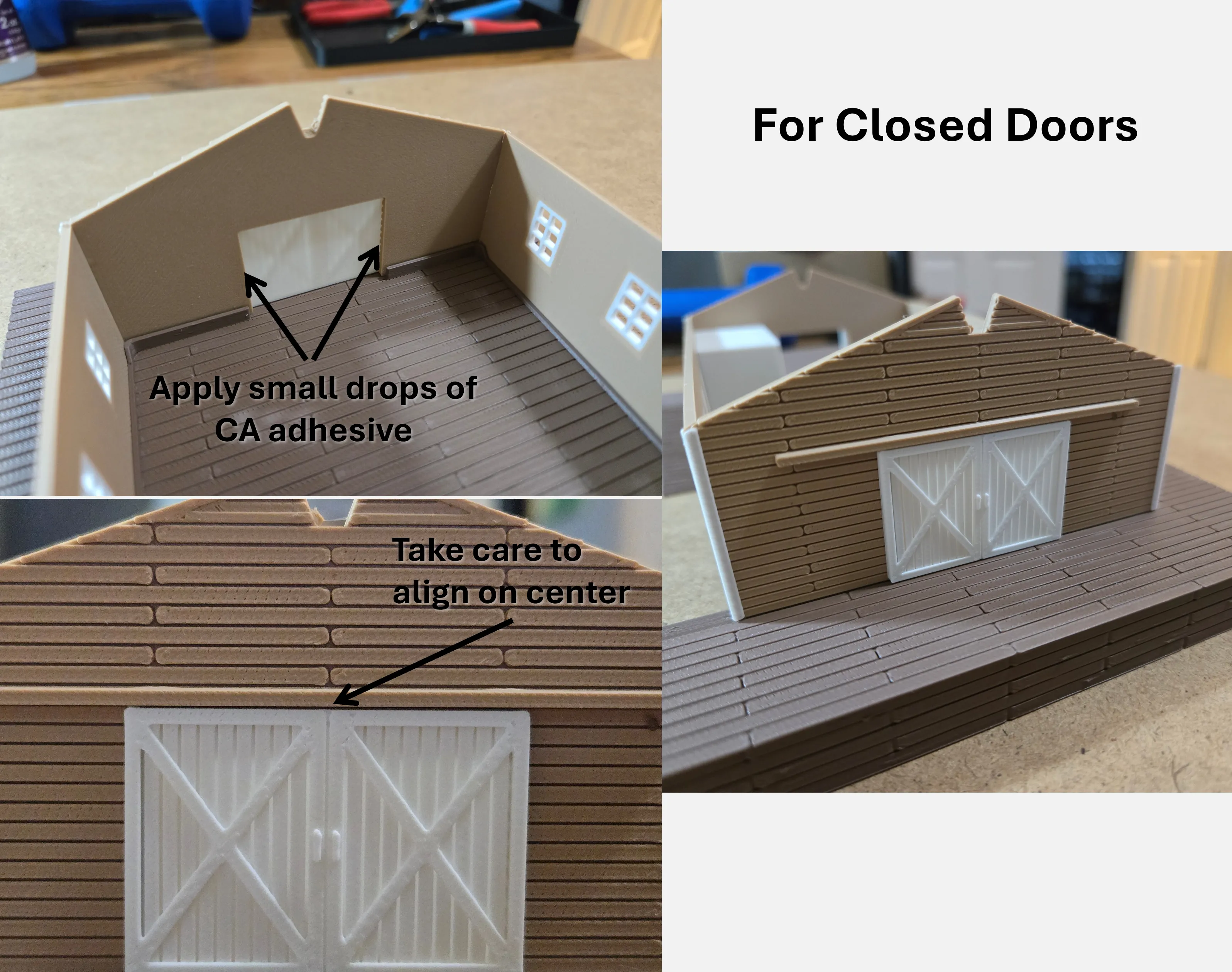
Step G - attach your choice of sliding doors, either Single Doors (6) or Closed Doors (7) to the Front and Back walls (4) using glue. Important note, the single doors have door handles that are intended to face the middle of the door openings of the walls. Unfortunately, these doors are too small to be functional with an ability to slide left or right so you need to decide if you want open or closed doors, and if open, how far open or closed each door is to be. When deciding on open or closed doors, think about where you will place this depot in a scene on your railroad and what might be going on in the scene, whether transferring freight between a train car through the front door opening or maybe moving freight out through the back door to a truck pulled up to the dock.
Are you thinking about modeling freight in your scene? Depending on a choice of options for attaching the roof (removable or not), this might be a good time to place any modeled freight within your depot, and when doing so, consider how it will be seen through the open doors and windows.
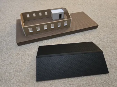
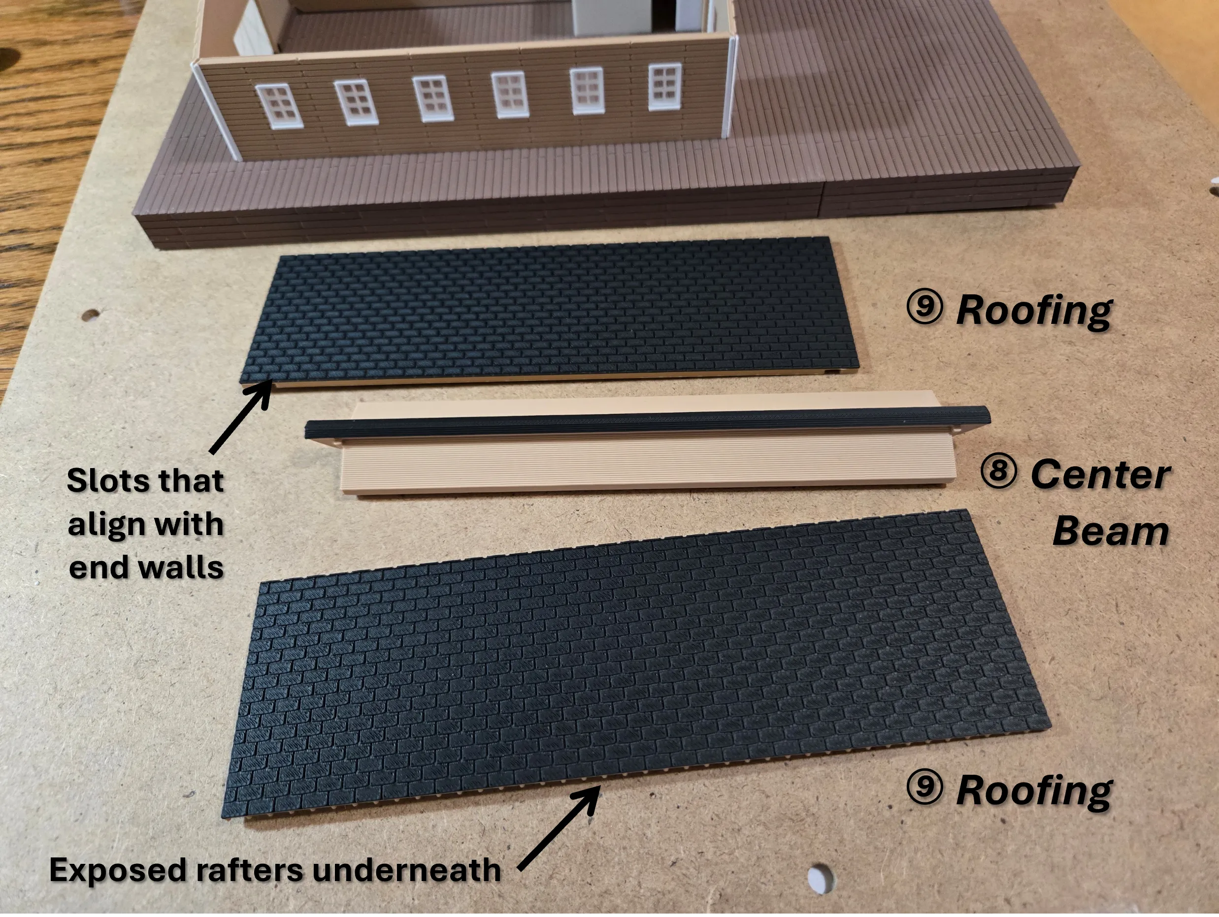
Roofing options - two assembly options are available to choose, either assemble the roof fully-attached to the depot or assemble the roof as a separate piece that can be easily installed and removed for access to the depot interior. Step H1 will be the removable roof option and Step H2 will be the fully-attached roof option.
I do find that the fully-attached roof option helps to assure a nice finished fit with all of the walls whereas the removable roof option is bound to sit somewhat lifted up along the side walls. Note: One option for helping to hold the removeable roof assembly in place is to use a repositionable tacky glue on the underneath of the roof panels where the align with the side walls … I have often used this Accents Glue from Woodland Scenics, https://woodlandscenics.woodlandscenics.com/show/item/A198, with good success for holding scenery objects in place without permanently bonding them down.
Step H1 (the removable roof option) - this option involves gluing the two Roofing (9) panels to the Center Beam (8) as a separate assembly, and then being able to position and “install” the roof onto the depot with the option to remove it at any time that you want to access the interior of the depot. Before gluing the roofing panels onto the beam, test fit each panel to see how it aligns with the top edge of the panel fitting snugly in “under” the asphalt section of the center beam without a noticeable gap. You will note that I used a generous amount of glue to help assure that the roof assembly will stay together with many insertions and removals.
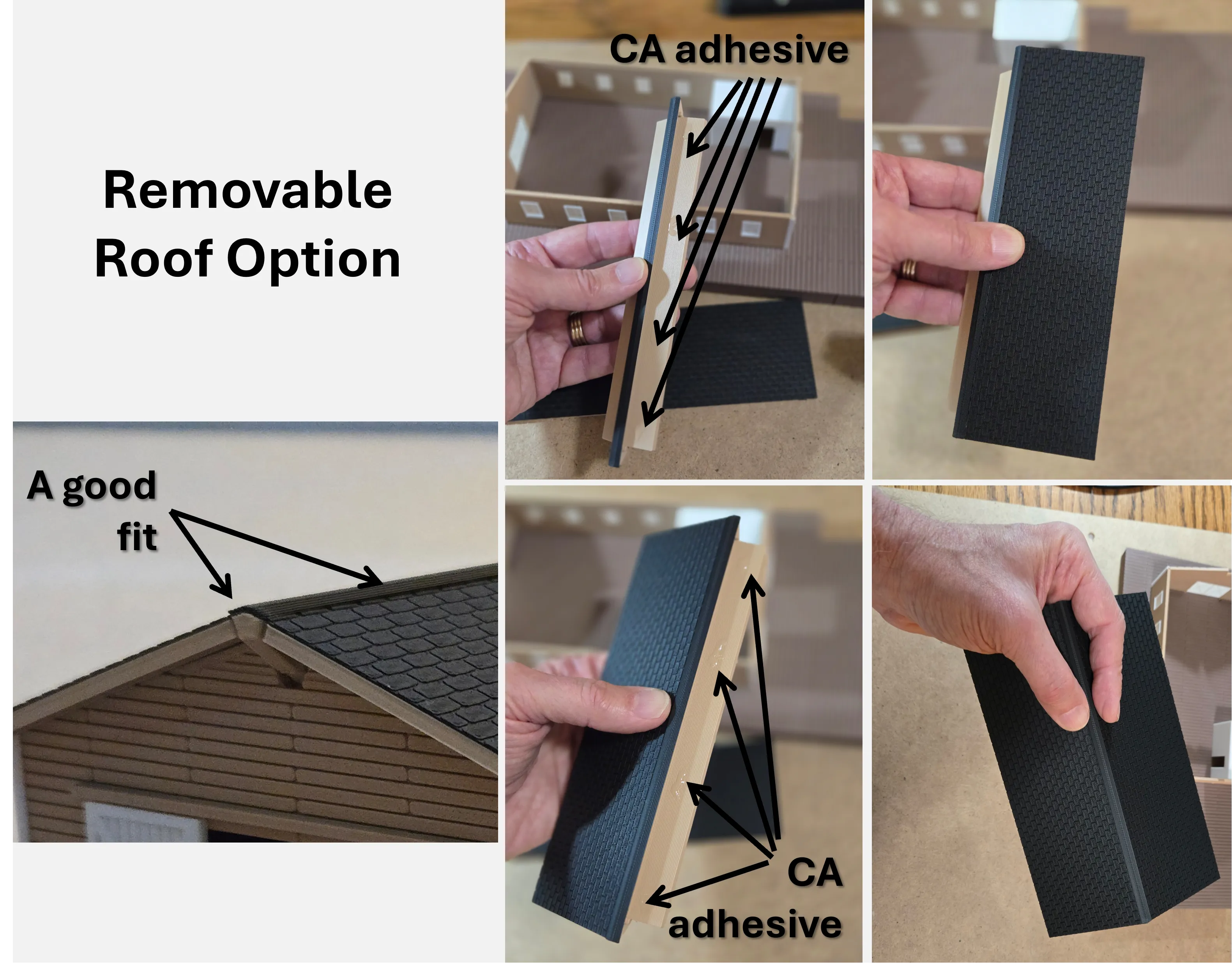
To install the roof assembly on your depot, simply insert the center beam over the structure with the beam centrally aligned between the V-slots of the end walls. Take care to settle the roof assembly in place with a good fit down onto the side walls.
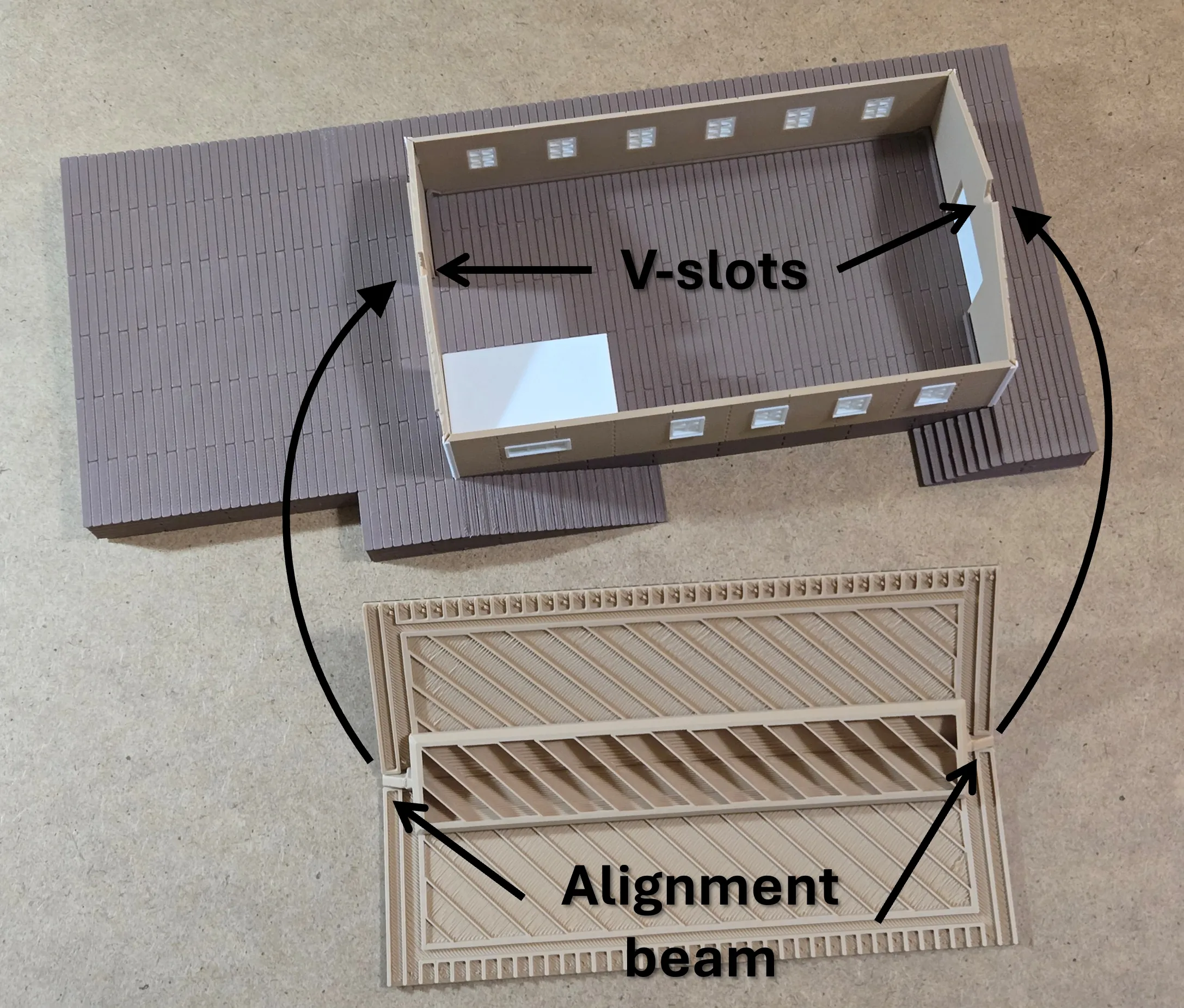
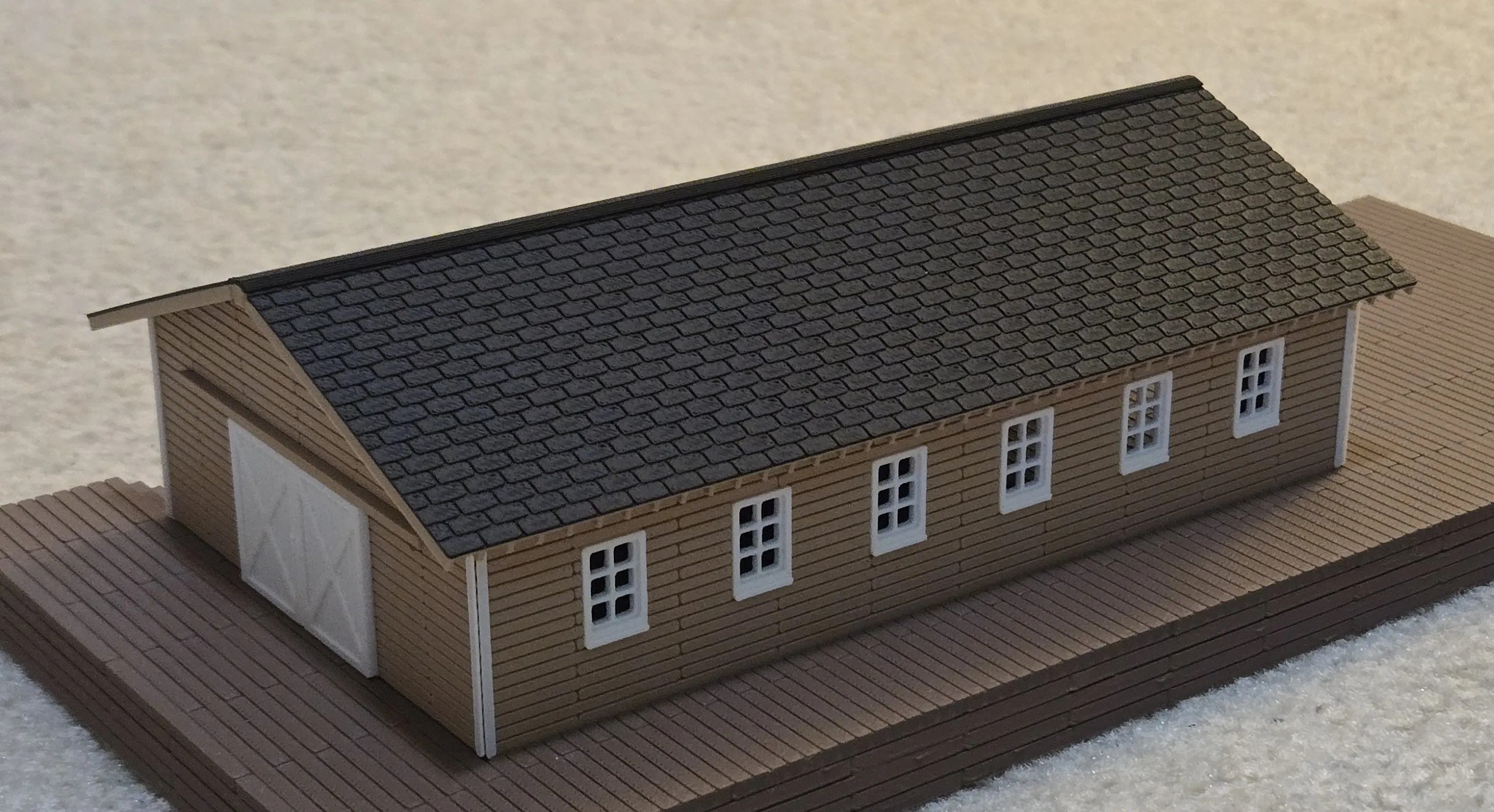
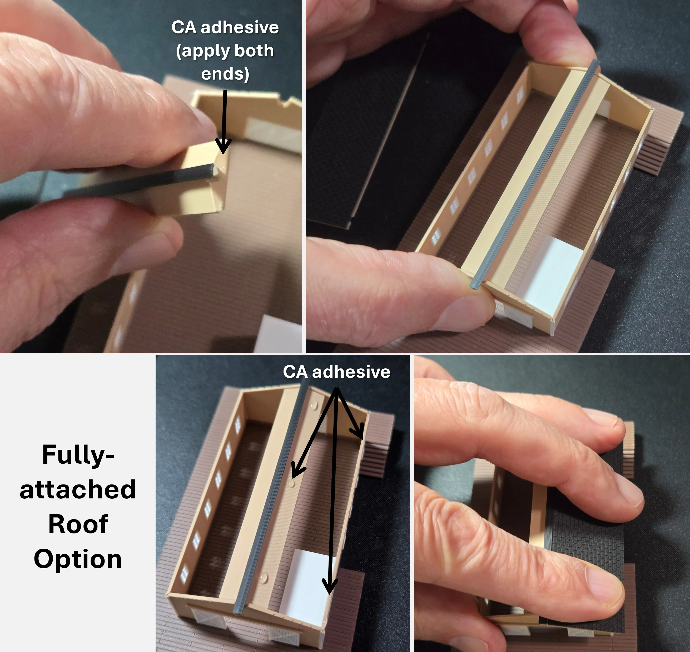
Step H2 (fully-attached roof option) - this option involves gluing the Center Beam (8) into the alignment V-slots provided at the top center of both the Front and Back walls (4). Before gluing into place, test fit the beam between the walls to first see how it all lines up with the flat upward surfaces of the beam sitting just a bit below the top edge of the walls. Once the beam is glued in place, test fit each of the Roofing (9) panels, making sure that the underside rafter ends are positioned outward from the structure - a proper fit should have the top edges of the side and end walls fitting into gaps that are on the underside of each panel. After test fitting to see how it is supposed to fit together, glue on each roofing panel, taking care to assure that the top edge of the panel fits snugly in “under” the asphalt section of the center beam without a noticeable gap.
Note: This illustration shows the fully-attached assembly option using the Z-scale version of the depot
but the process is the same for the HO-scale model but will obviously take both hands 😁
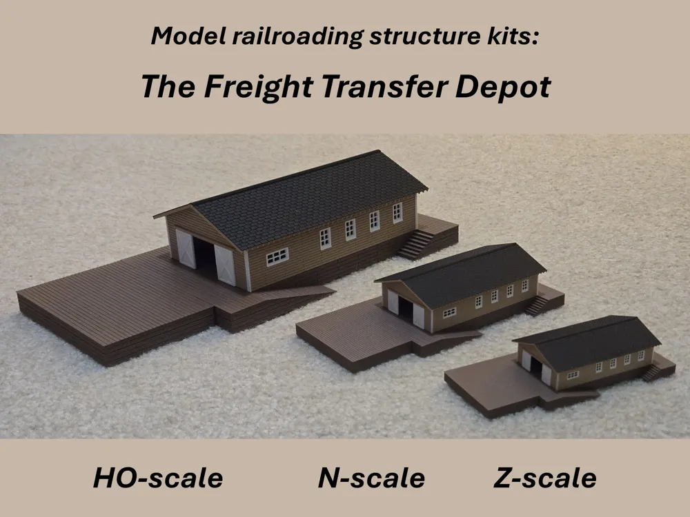
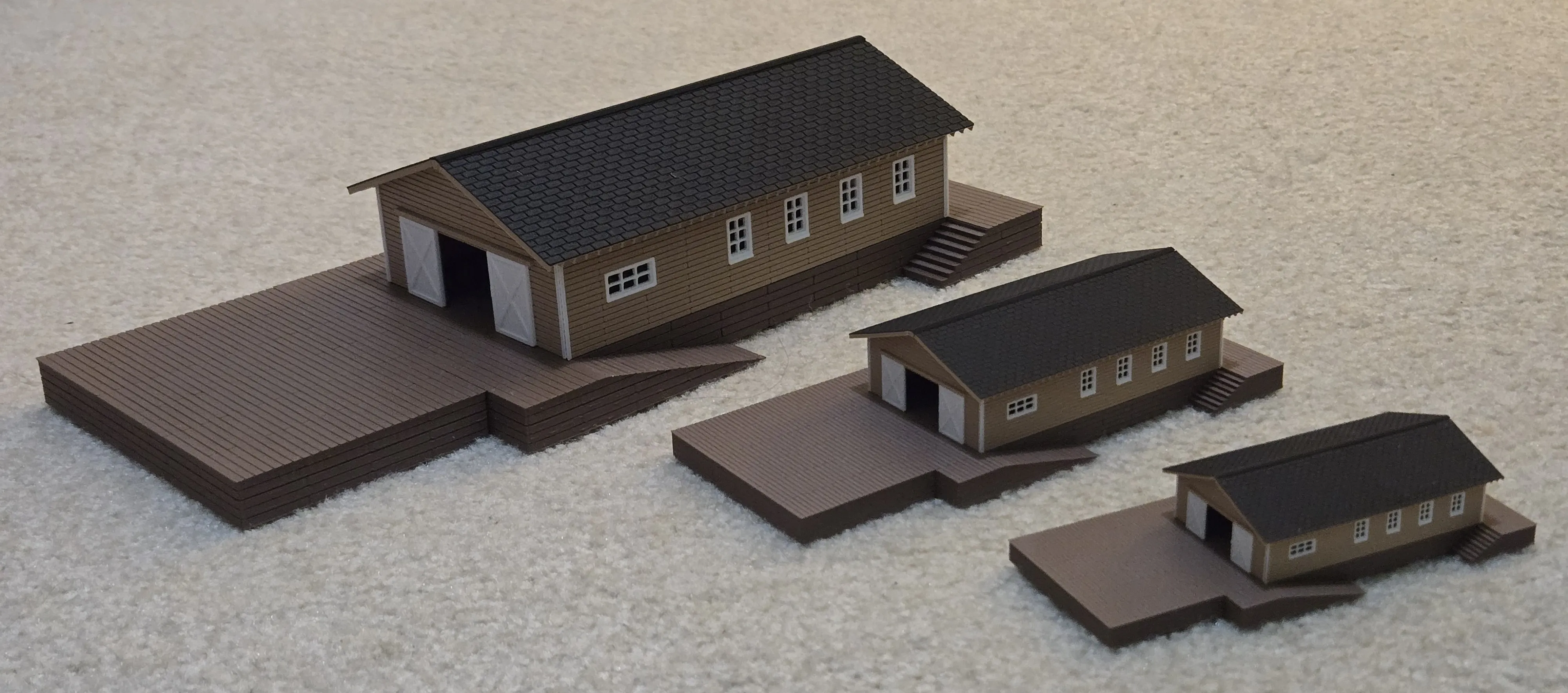
The finished models in HO-scale, N-scale and Z-scale.
I hope that copies of this model find good homes on model train layouts around the world … if you are careful and patient, you should be able to produce a nice looking structure … have fun with it!
Boost Me (for free)
Model developers like myself can always do with a bit of encouragement. Posting a rating with pictures, tagging our models with a Like, or even giving us a Boost is always appreciated. Thanks!
License

You shall not share, sub-license, sell, rent, host, transfer, or distribute in any way the digital or 3D printed versions of this object, nor any other derivative work of this object in its digital or physical format (including - but not limited to - remixes of this object, and hosting on other digital platforms). The objects may not be used without permission in any way whatsoever in which you charge money, or collect fees.


Comment & Rating (0)