Parametric CRBOX Air Purifier IKEA STARKVIND


Print Profile(1)
Bill of Materials

Description
Parametric CRBOX Air Purifier using IKEA STARKVIND
Boost Me (for free)
Boosting will give more visibility encourage more mods and newer revisiones.
READ ALL INSTRUCTION BEFORE PRINTING! THERE'S REQUIRED MANUAL SLICER STEP BEFORE PRINTING.
This is a first DIY version, except some manual assembly and hot glue action.
Introduction

This is a fully parametric corsi rosenthal style crbox using 4 IKEA STARKVIND filter (HEPA 12, it captures 99.5% of airborne particles like dust, pollen, and PM2.5) and 4 Artic P14 Pro PST fan, PWM controllable for silent operation AND ultra-high filtration at max speed.
This project started as while there's model for MERV-13 filter (furnace filter), which filter about only ~50% to 75% of particles, but offer much less air resistances, thus allowing more air to pass the filter, those filters are not commonly available outside the NA, thus IKEA STARKVIND was chosen as a widely available and at very affordable price.
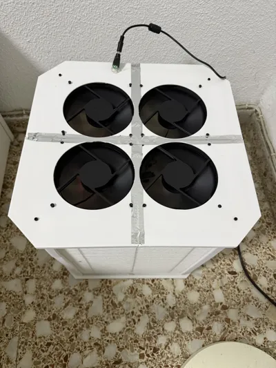
Here's my PM2.5 sensor with the crbox fan running at constant 27% (zero audible noise for me) with windows open all day and night, guess when I finished this project.

Before building the air purifier, there's some reading about how an air purifier work.
For the 3d printable part, mainly there are 3 modules, the top plate, where we mount the fans, the middle module is columns that hold filters in place, and bot plate that is like top plate but without the fan cutout.
Here's some human approved and edited diagram for visual aid.

The airflow direction is FILTER → FAN, with the fans arrows pointing outward.

Now that we know what parts to expect, due to the printer size, I have decided building a tall tower and divide it in parts with allow 2x2x140mm fan, with a wide tower configuration, 3x3x120mm fan configuration should be possible (try it in parametric builder!).
Print instruction:
After generating the parametric model, it gets imported as single file, you need to split it into multiple object in slicer (or use the profile already separated). It applies to column and plates

Model assemble instruction
All the instruction below assumes tall tower using 4 x STARKVIND and 4 x P14 Pro PST, alteration is possible thanks to the parametric builder, feel free to ask for any question.
The STARKVIND filter (without active carbon) contrary of the measure from IKEA, is 5mm less in each side, resulting 365x285x35mm, with a thin 2mm foam as padding on height and width.
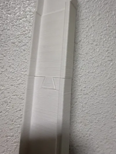
The column frames are divided as 3 section, allowing arbitrary height build as the rotatory dovetail connector is the same for all 3 parts so it's possible to chain multiple middle column section.

I have printed with white PETG using 0.6 nozzle with thin tree support, so the tolerance requirement should be low.

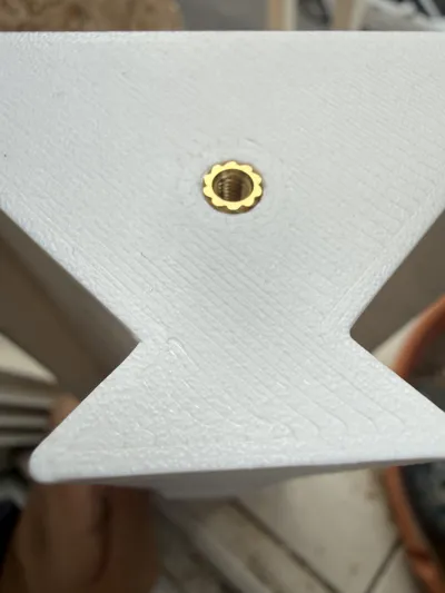
At the base and top column component, there's a M3x6mm with 5mm OD (VORON) heat insert for securing it to the base and top plate, this step is technically optional, as friction should clamp it together, but due to 2mm foam in the filter, using a fastener allow it to be more airtight increasing the efficiency by maintaining higher negative pressure.

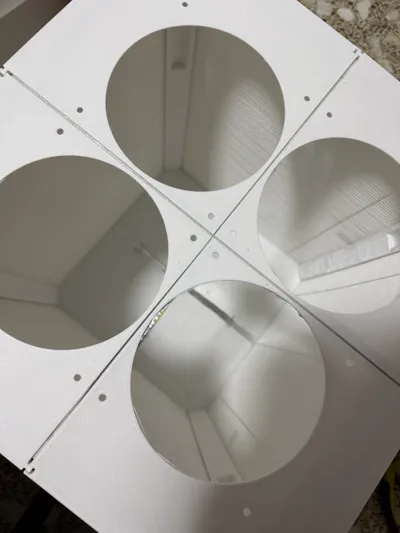
After printing the 4 set for columns, the next step is printing the base and top plate, those should be printed with 2+ wall and 3 bottom and top layer to add structure integrity as it's only 2mm thin.
Due to designing for the maximum compact, the top plate have no cutout for cable going outside, do it in the slicer as negative part (only 1 of 4 top plate need this cutout), or you will need to drill it later. I have opted a 10mm diameter circle near the wall, above the filter, thanks to the foam, there is a bit of gap, check the final assembly for reference.
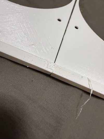
At the ridge, there's dovetail connector to lock it in by friction alone.

With the top plate assembled like this:

And we can test fit with the column frame, the top column have a notch for the fan, for final assembly screw the bot plate with bot column first (after sealing it with foils in later steps).

[OPTIONAL] To add more rigidity I have used plastic stapler, on the bot plate we can stapler almost anywhere, but be careful to not interfere the top plate fan, you need to cut the legs so it doesn't interfere with the filter..

[REQUIRED] Due to the imperfection of 3d printing, there are small gaps at the edge, use HVAC self-adhesive aluminum tape to seal it, you can see the tape in the end result.
Finally, the structure part is finished, we need to wire it.
There are two versions, the soldering required smart home ZigBee version using ESP32-C6 as PWM controller or no soldering, a manual DC 12V PWM Speed Controller with a knob. Personally I went with ZigBee version as I want to control it in home assistant and pair it with air quality sensor.
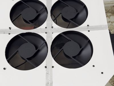
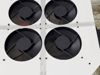
First we need to mount the fan to the top plate, be careful of the direction, the arrow on the fan should match the airflow in the above diagram (Outward) change daisy chain them together using the included PST cable, leave the input header near the hole you make in the top plate. Press the fan and top plate hard together to leave no gap, pre-tapping the screw maybe is a good idea.
This is the fan header pinout, watch for the arrow for Pin 1.

ESPHOME Version/ Zigbee / Thread / WiFi
The wiring for Esphome version is more complicated are we need to buck 12V to 5V for ESP32-C6. In this case I have chosen UPDATED TO NEW ESPHOME VERSION, GPIO0 for PWM (yellow cable to GPIO0 instead of GPIO4), and optional RPM count to GPIO1 (the last pin in fan header to GPIO1).
BEFORE CONNECTING ESP32, MUST ADJUST BUCK CONVERTER TO 5V WITH A MULTI-METER!
Feel free to use another DC buck converter if available, just watch out as LM2596 is not isolated so it shared ground between ESP32 and the fan, which is what we want, use male DuPont to connect fan header.

Remember to flash the ESP32-C6 before final assembly. I will provide the code for ZigBee version (which emulate as a RGB lamp for floating fan speed control, a bit hacky for my taste, maybe I will migrate to thread/matter), but ESPHOME is recommended if you don't mind using Wi-Fi.
Manual 12V PWM Fan controller version
In this case, connect the 12 DC Input to the two wire of the controller and connect the fan header, make sure to leave the controller outside the crbox if you want to access it later (or just leave at a constant low speed for 0 noise), there's no mount and hot glue is required.
For the actual connection, ferrule crimp is recommended, but hot glue can work too..

BOM
Both version:
1.5KG of filament (PETG recommended, but PLA should work too).
4 x IKEA STARKVIND Filter https://www.ikea.com/es/en/p/starkvind-filter-for-particle-removal-30461943/
4 x Artic P14 Pro PST (Buy a pack of 5 fan) https://www.amazon.es/ARCTIC-P14-Pro-Piezas-Hidrodin%C3%A1mico/dp/B0DPX94PSL
1m x 5cm Seal self tape aluminum foil https://es.aliexpress.com/item/1005009393671611.html
8 Pieces of M3*6*5 OD(VORON size) heat inserts, here's the kit I'm using, 100pcs M3 https://es.aliexpress.com/item/1005006472962973.html
8 Pieces of M3*8 screw (The kit I'm using, 392pcs M3) https://es.aliexpress.com/item/1005007159750547.html
1x 12V DC power supply 2A minimum (I would get 3A+, with my smart plug it measures 17W at max fan speed) Probably overkill, but I recommend and using 5A version, MEAN WELL GST60A12-P1J as it offer many protections (Yeah I have shorted it accidentally when wiring and it worked perfectly) and have near 90% efficiency, which for a 24x7 device the different in electricity will pay itself. https://es.aliexpress.com/item/1005006730276399.html and if going budget option, this 12V3A version is sufficient https://es.aliexpress.com/item/1005007418567989.html
1 Piece female 5.5x2.1mm Power plug jacks sockets https://es.aliexpress.com/item/1005006265396074.html
Tools:
Heat insert press, I have an T12 soldering iron and I bought a heat insert adapter, it seems there's adapter for “old school” 936 connector as well https://es.aliexpress.com/item/1005010186238310.html
2.5mm Hex key for the M3 screw, it should come with the M3 screw kit I linked.
Phillips screwdriver for tapping M4 screw from the P14 Pro PST fan (I think PZ1 is good enough).
Hot glue gun for sealing the wire hole.
ESP32-C6 version:
1 x ESP32-C6-N4 dev board https://es.aliexpress.com/item/1005007036161205.html
1 x LM2596 Adjustable DC to DC Step Down Buck Converter https://es.aliexpress.com/item/1005010001439374.html
Wires for soldering this connection, as for connecting the fan header, male DuPont wire is required, get 22AWG cable if using same wire for 12V fan input https://es.aliexpress.com/item/1005006253081415.html the alternative is crimping the wire yourself.
[OPTIONAL] Some wire connector, I prefer this kit https://es.aliexpress.com/item/1005008462831423.htmlheat shrink, the alternative is some butt connector or just soldering and heat shrink.
Tools:
Multimeter, required for adjusting 5V to LM2596.
Soldering iron for connecting LM2596 and for header pin of ESP32-C6
Manual PWM control version:
1 x DC 12V PWM Speed Controller: https://es.aliexpress.com/item/1005004904458737.html
Any question feel free to comment and ask.
Parametric base sketch
This is the base sketch of the column for the IKEA tall tower design, can be helpful to cross-reference and customize your own parametric design.

ESPHOME Firmware
I have since moved from raw ESP-IDF project to ESPHOME as the original firmware require modification to Zigbee2MQTT config to expose the device entity as lamp disguising speed as brightness control. And I think anyone with Zigbee2MQTT can install ESPHOME without problem.
The ESPHOME version allow Wifi, Zigbee, and Thread, modify the connection info to adapt it. I have added code to avoid the noisy frequency ~1000RPM. By default it use GPIO 0 for PWM and GPIO1 for optional pulse counter (connect the third pin in fan header).
Comment & Rating (8)