Modular PCB Case


Print Profile(5)

Bill of Materials


- M2x8mm Schraube x 4: Schrauben zur Befestigung der Füße mit der Bodenplatte
- M3x6mm Schraube x 4: Schrauben zur Befestigung der PCB mit der Bodenplatte.
- M3x6-8mm Schraube x 5: Schrauben zur Befestigung des Gehäuse mit der Bodenplatte.
- M3x4.6x5.7 Gewindeeinsatz x 9: Gewindeeinsätze zur Verschraubung des Gehäuse mit der Bodenplatte sowie der PCB.
Description
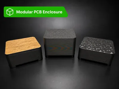
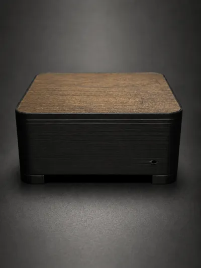
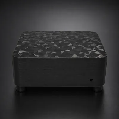
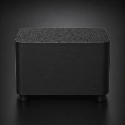
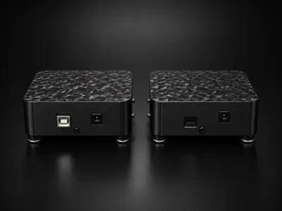
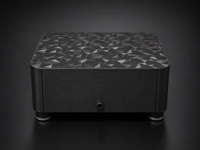
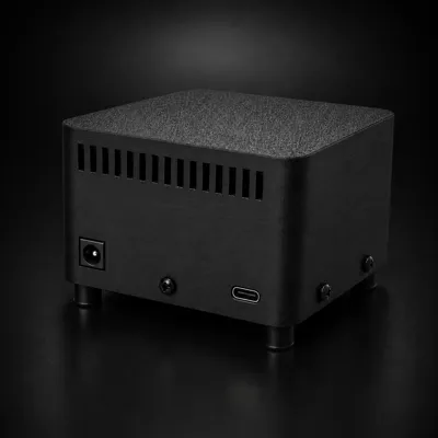
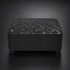
Modular PCB enclosure with three variants: a tall enclosure measuring 100 mm × 100 mm × 60 mm, a flat set-top box enclosure measuring 100 mm × 100 mm × 35 mm, and a flat acrylic & wood set-top box enclosure measuring 100 mm × 100 mm × 40 mm. The electronics are mounted on the base plate. The enclosure shell, PCB, feet, and optional TPU dampers are functionally separated. The design is easy to maintain, screwed together, and suitable for small embedded, microcontroller, and prototyping projects
Key Features
- Three enclosure variants:
- tall enclosure measuring 100 mm × 100 mm × 60 mm
- flat set-top box enclosure measuring 100 mm × 100 mm × 35 mm
- flat acrylic & wood set-top box enclosure measuring 100 mm × 100 mm × 40 mm (Inlay : 97.5 x 97.5 mm)
- Base plate for mounting electronics
- Four PCB standoffs with M3 threaded inserts
- Screwed connection of the enclosure shell to the base plate
- Optional separate universal enclosure shell with adaptable I/O shield
- Printed PLA feet
- Optional separate TPU dampers
- Ventilation slots in the base plate and on the back
- Rounded enclosure edges
- Suitable for small PCB, controller, and embedded projects
Construction

The model consists of several functionally separate components:
| Component | Description |
|---|---|
| Enclosure shell | Outer cover of the enclosure |
| Base plate | Support structure for PCB, threaded inserts, feet, and enclosure mounting |
| PLA feet | Printed feet for stable placement |
| TPU dampers | Optional separate damping elements |
Required Parts
Screws and threaded inserts
| Part | Quantity | Usage |
|---|---|---|
| M2×8 mm screw | 4 | Mounting the feet to the base plate |
| M3×6 mm screw | 4 | Mounting the PCB to the base plate |
| M3×6–8 mm screw | 5 | Mounting the enclosure to the base plate |
| M3×4.6×5.7 threaded insert | 9 | Screwing enclosure, base plate, and PCB |
Assembly Principle
First, the threaded inserts are placed into the base plate. Then, the feet are screwed to the base plate. Afterwards, the PCB can be directly attached to the base plate. Four raised standoffs are provided for this purpose. Next, the enclosure shell is placed over the base plate, hooked in, and screwed to it. See Quick Guide
Standard PCB Drilling Pattern

Material Recommendation
| Component | Recommended Material |
|---|---|
| Enclosure shell | PLA or PETG |
| Base plate | PLA or PETG |
| Feet | PLA |
| TPU dampers | TPU |
For normal indoor electronics projects, PLA is sufficient. For higher temperature loads, continuous operation, or installation in warmer environments, PETG may be useful for the enclosure shell and base plate
Printing Instructions
- Recommended layer height: 0.20 mm
- Nozzle: 0.4 mm
- Infill: approx 15 %
- Wall lines: 2
- Support: depends on orientation and print profile
- The threaded inserts are thermally inserted after printing
- The TPU dampers are optional and not identical to the PLA feet
Suitable for
- Microcontroller projects
- ESP32/ESP8266 applications
- Sensor boxes
- Smart home gateways
- Small network or control devices
- Prototyping setups
- Compact embedded systems
- Small audio, LED, or automation projects
Comment & Rating (0)