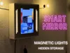
SmartMirror Organizer


Print Profile(2)

Bill of Materials


- spray bottle x 1: to apply soapy water
- mirror film x 1: min. 400x400mm
- 3x300x300mm Acryl Plate x 1: for the film
- Nail x 6: for hanging
Description
The SmartMirror Organizer combines modern smart-home aesthetics with practical everyday functionality.
You didn’t want to just throw your keys and valuables into a boring bowl, right?
You wanted a smart mirror that can display everything for you with just a few voice commands — while also looking stylish and providing ambient lighting?Then you’ve come to the right place with my SmartMirror Organizer.
At first glance, it looks like a clean, minimalist wall mirror — but hidden behind the spy mirror is a fully integrated tablet that transforms it into a futuristic smart display. Perfect for widgets, weather, music, calendars, reminders, or your favorite apps.
But this project is more than just a smart mirror.
Integrated magnetic light controls allow the side lights to be turned on and off in a satisfying and almost “magical” way, while hidden compartments keep important everyday items safely out of sight.
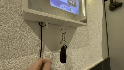
Keys can also be attached magnetically underneath the organizer, keeping them easily accessible while maintaining the clean and minimal design. Additionally, the entire organizer can be slightly lifted from the wall and mounted lower onto a secondary hidden position, revealing extra secret storage space — perfect for a wallet, cash, cards, or other important items.
The combination of warm ambient lighting, hidden mechanisms, smart functionality, and modern design makes this project perfect for:
- Smart home setups
- Entryways & hallways
- Gaming or desk setups
- Minimalist interiors
- DIY and tech enthusiasts
The SmartMirror Organizer was designed to feel modern, futuristic, and practical at the same time. This makes it not only a useful everyday organizer, but also a real eye-catching conversation piece.
Below you will now find a detailed step-by-step build guide, including all required printed parts and components. Of course, all necessary parts are also included in the parts list.
However, before getting started, please note that in addition to the MakerWorld parts, you will also need:
- A privacy mirror film / spy mirror film
- One 300x300x3 mm acrylic sheet
- And of course, a tablet for the smart mirror functionality.
Boost Me (for free)
Thank you

Step 1 – Preparing the Electronics
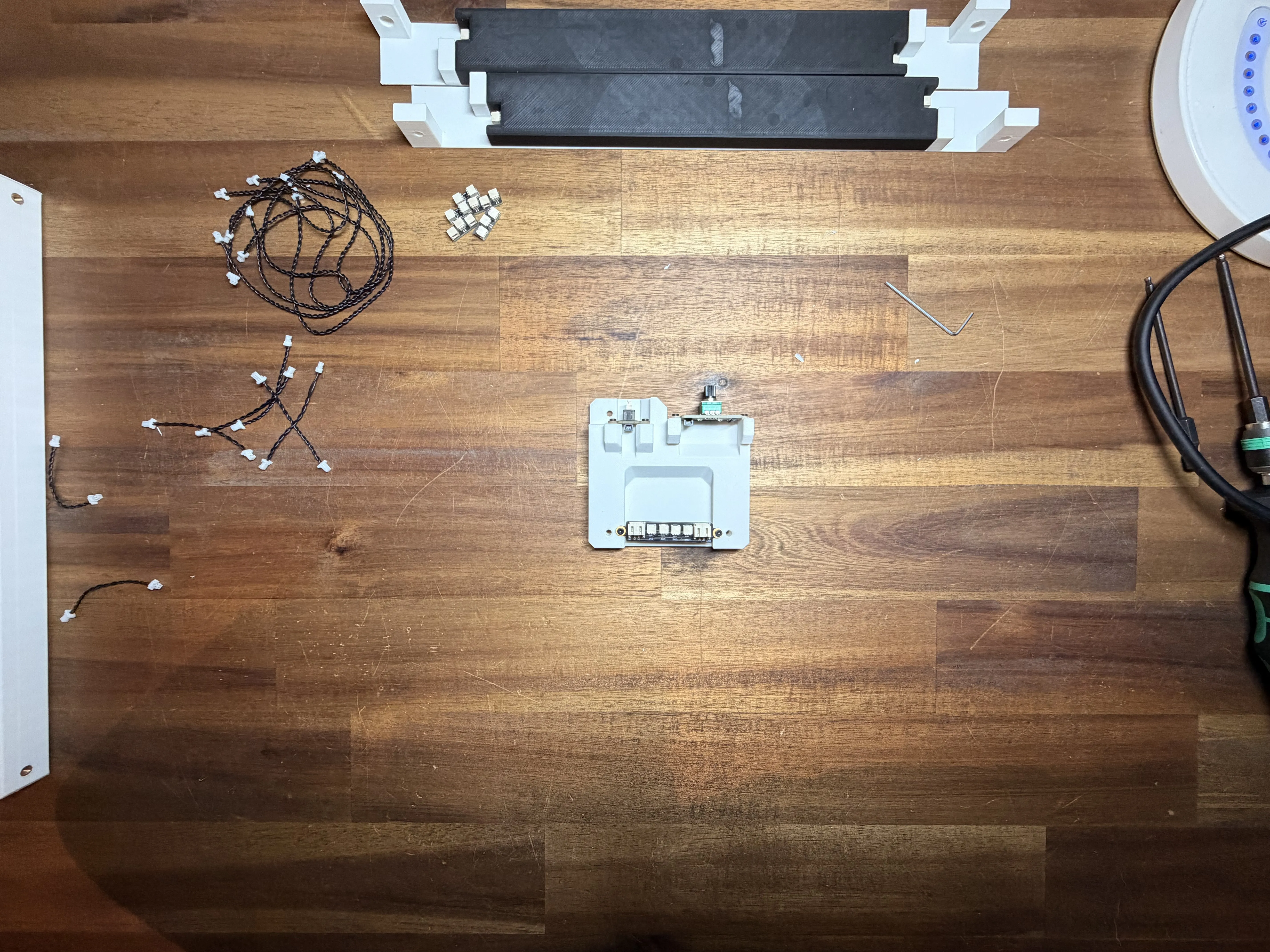
First, we will start with the electronics.
All required components can be found in the parts list, so place everything on your table and make sure nothing is missing.
You will need a few basic tools:
- Soldering iron
- Allen keys / hex drivers for the screws
The soldering iron will be used to melt the threaded inserts into the 3D-printed parts. This makes the assembly much stronger and allows the screws to fit properly.
⚠️ Safety Tip:
The soldering iron gets very hot, so always be careful while using it.
Before continuing, make sure your workspace is clean and all parts are ready.

Step 2 – Installing the Threaded Inserts
Now start with the black printed parts.
As shown in the picture, melt the threaded inserts into the holes on the left and right side.
You will need a total of 4 threaded inserts for this step.
Use the soldering iron carefully and slowly press the inserts into the plastic.
Make sure the inserts are completely inside the part and sit perfectly flush with the surface. Do not leave them sticking out.

Step 3 – Installing the Lights
Now insert the 200 mm LED lights into the printed parts.
Before installing them, it is a good idea to test if all lights are working properly.
I recommend using a small amount of super glue to hold the lights in place so they cannot fall out later.
You can also glue the circuit board directly into the part.
Make sure everything is positioned and fixed exactly like shown in the picture.

Step 4 – Joining the Parts Together
Now carefully flip the assembled part over and place it into the second printed part.
I recommend adding a small amount of super glue around the LED areas of the first part before joining both pieces together.
Then flip it over onto the second part and press everything together carefully.
Insert the screws on the left and right side and align everything properly before the glue dries.
At the beginning, the idea was to build everything without glue, but during testing it turned out that using glue works much better and also gives a cleaner final look.

Step 5 – Installing the Electronics
Now take the part shown in the picture and start mounting the electronics.
First, attach the circuit board to the printed part using M3x8 mm self-tapping screws.
Make sure the open connector ports are facing upwards.
Next, mount the button and the potentiometer on the top side.
These are also fixed using M2x8 mm self-tapping screws.
For this step, you will need a total of 6x M2x8 mm self-tapping screws.
Before tightening everything completely, make sure all parts are aligned nicely like shown in the picture.
Below you can see a picture of how the finished assembly should look for comparison.
Here is the picture for comparison. Make sure everything looks exactly like this and that all parts are firmly attached.

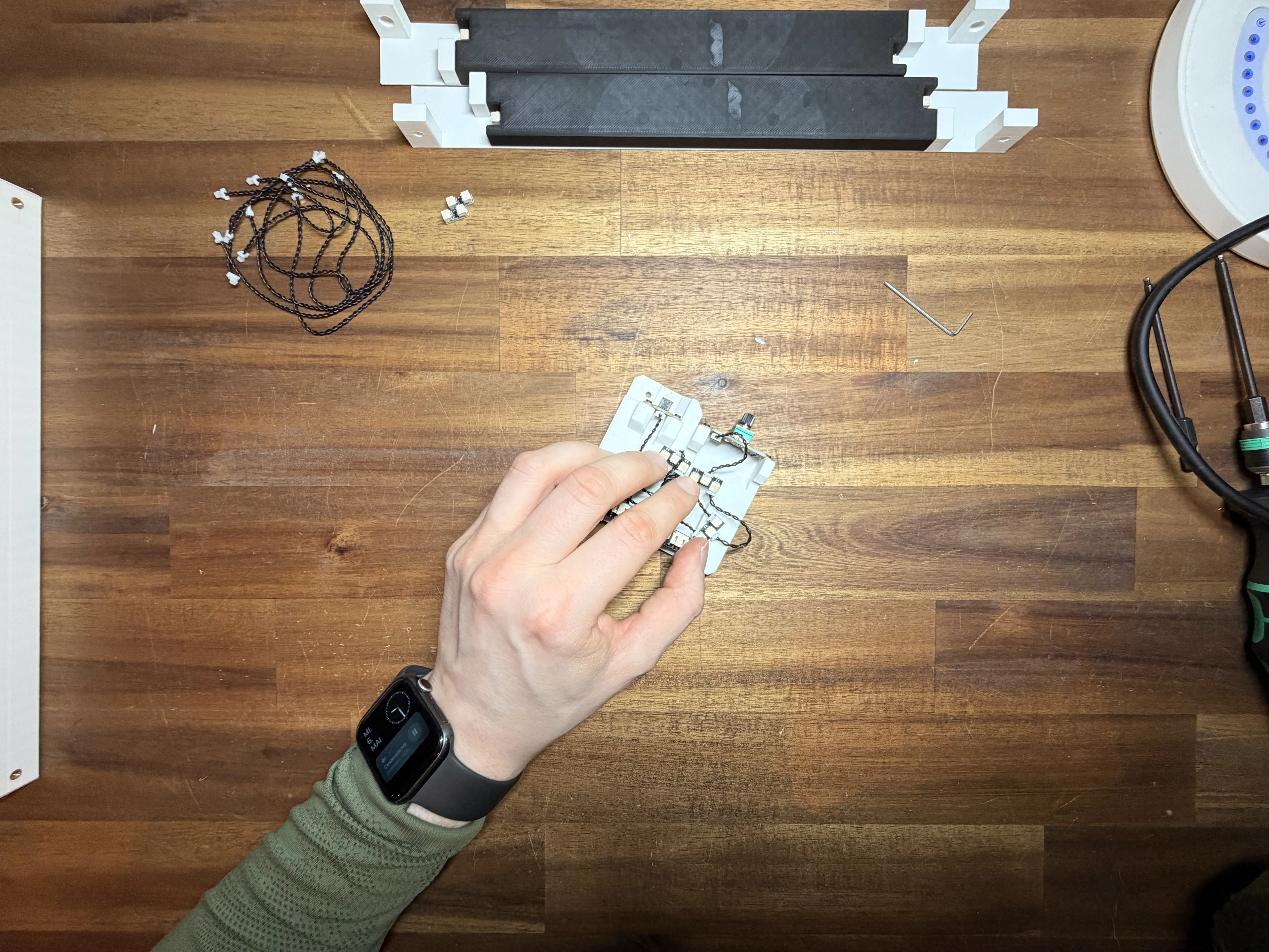
Step 6 – Connecting the Potentiometer
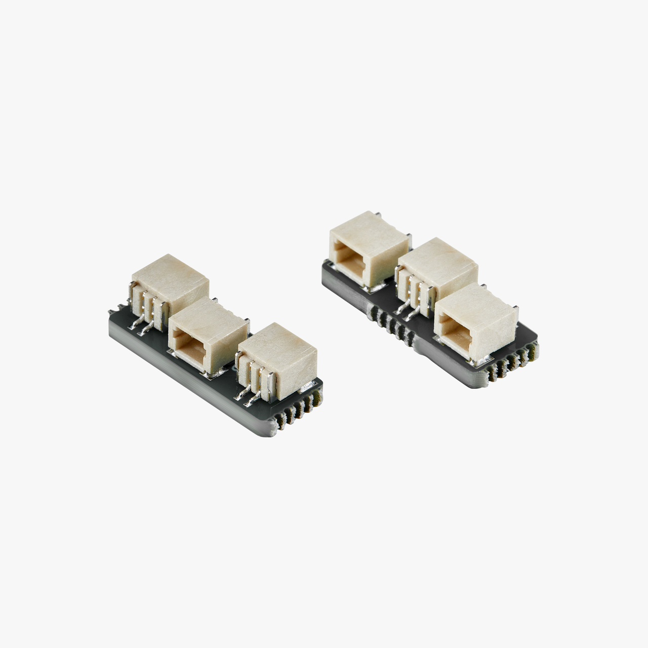
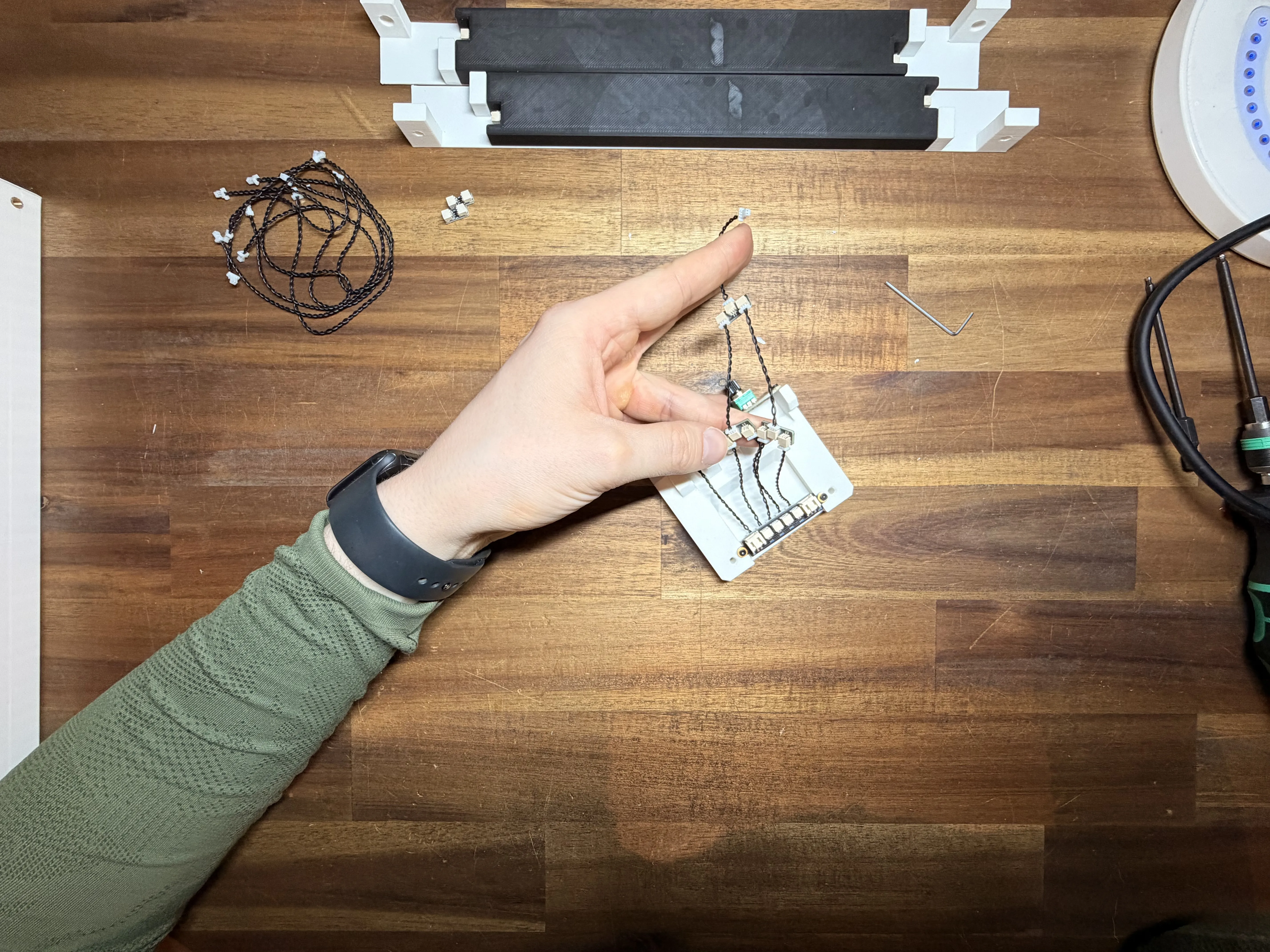
Now use the 50 mm long connector wires and plug them into the 4 connector ports on the black side.
Next, connect two neighboring wires together using the connector piece, exactly like shown in the picture.
With this setup, one single potentiometer can control all 4 inputs of the circuit board at the same time.
This allows you to adjust all 4 outputs together later with only one potentiometer.
Make sure all connections are fully inserted and firmly connected.
Step 7 – Wiring the Potentiometer and Button
Now connect both connector outputs again using two more 50 mm wires into another dual connector.
The final output of this connector will then be connected to the potentiometer.
With this setup, one single potentiometer signal is split across all 4 control inputs of the circuit board.
This means you can later control all 4 outputs at the same time with only one potentiometer.
Here is exactly how everything needs to be connected:
- SW0 → Connect the button here
- SW1 → Connect to the potentiometer
- SW2 → Connect to the potentiometer
- SW3 → Connect to the potentiometer
- SW4 → Connect to the potentiometer
The button must be connected to the very left input, directly next to the main power input on the board.
Make sure all connectors are pushed in completely and that no cable is loose.
After connecting everything, you can glue the small circuit boards into place like shown in the picture.
This keeps the wires and boards from moving around inside the case and gives the whole assembly a much cleaner look.
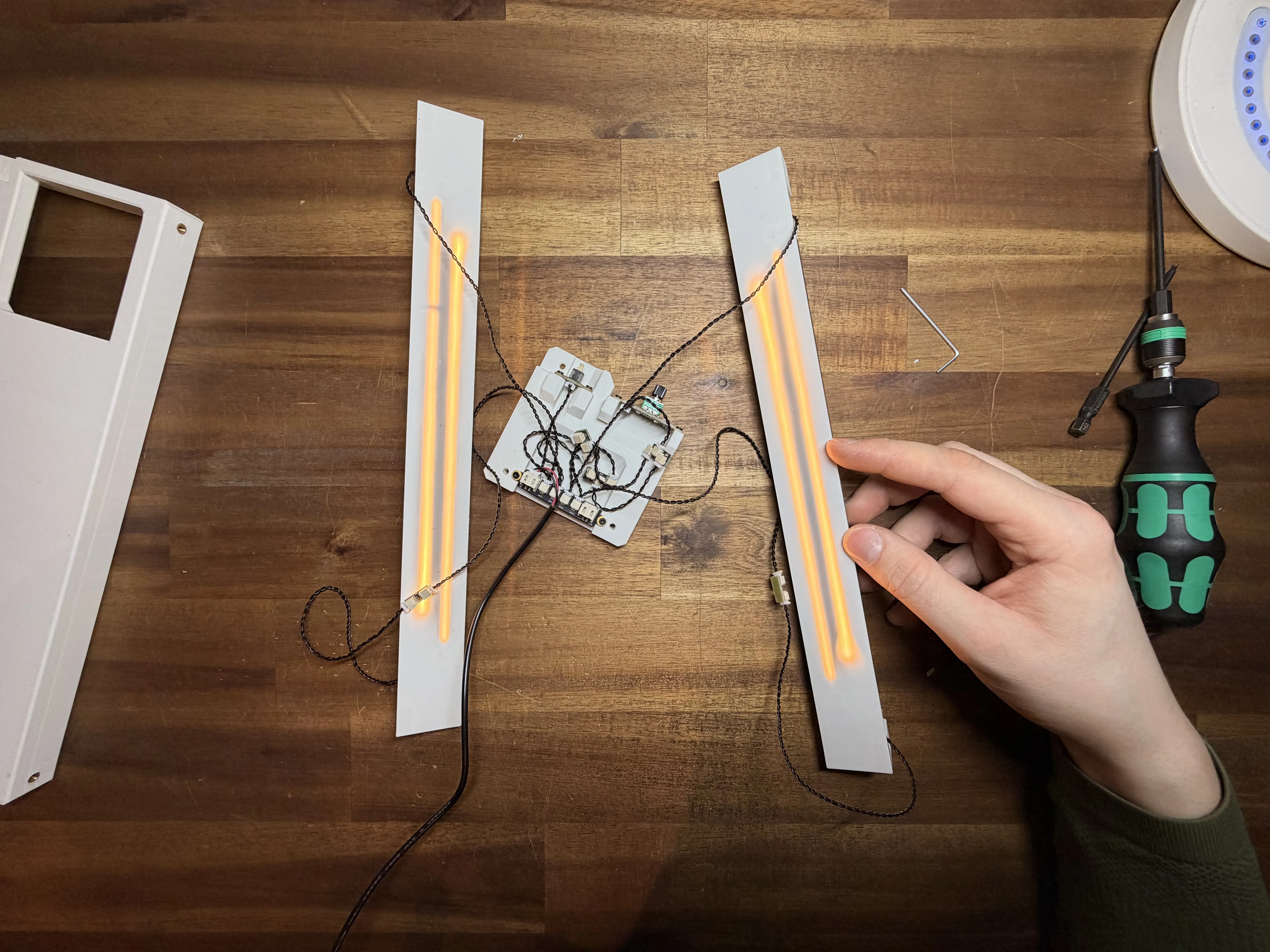
Step 8 – Connecting the LED Strips
Now it is time to connect the LED strips.
Connect the two upper LEDs using the 200 mm wires.
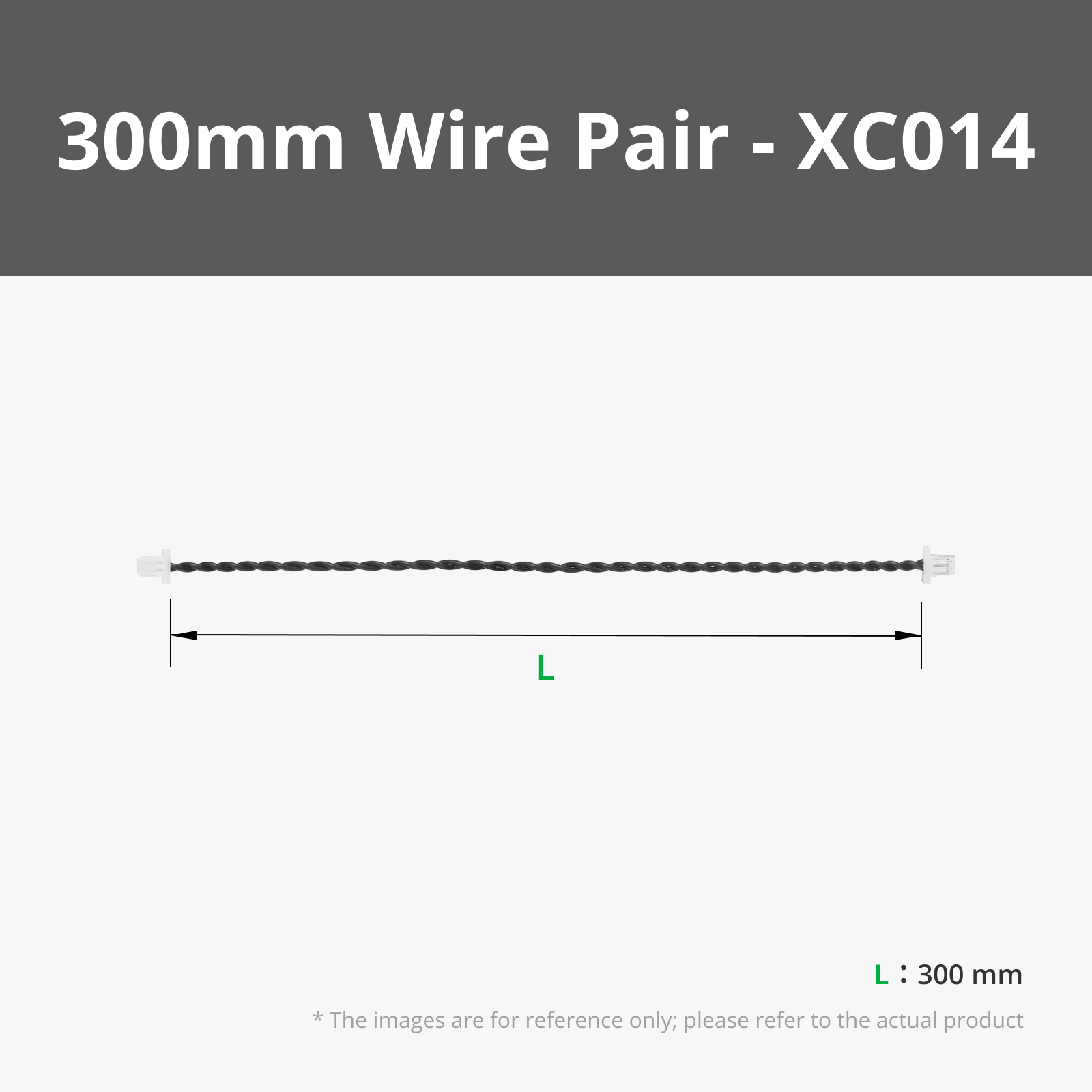
The two lower LEDs should be connected using the 300 mm wires.
On my build, you may notice that I used two 200 mm wires for the lower LEDs together with a small extension connector board.
That is only because I did not have 300 mm wires available at the time.
In the parts list, I already added the correct 300 mm wires, so your setup should be much cleaner and easier to build.

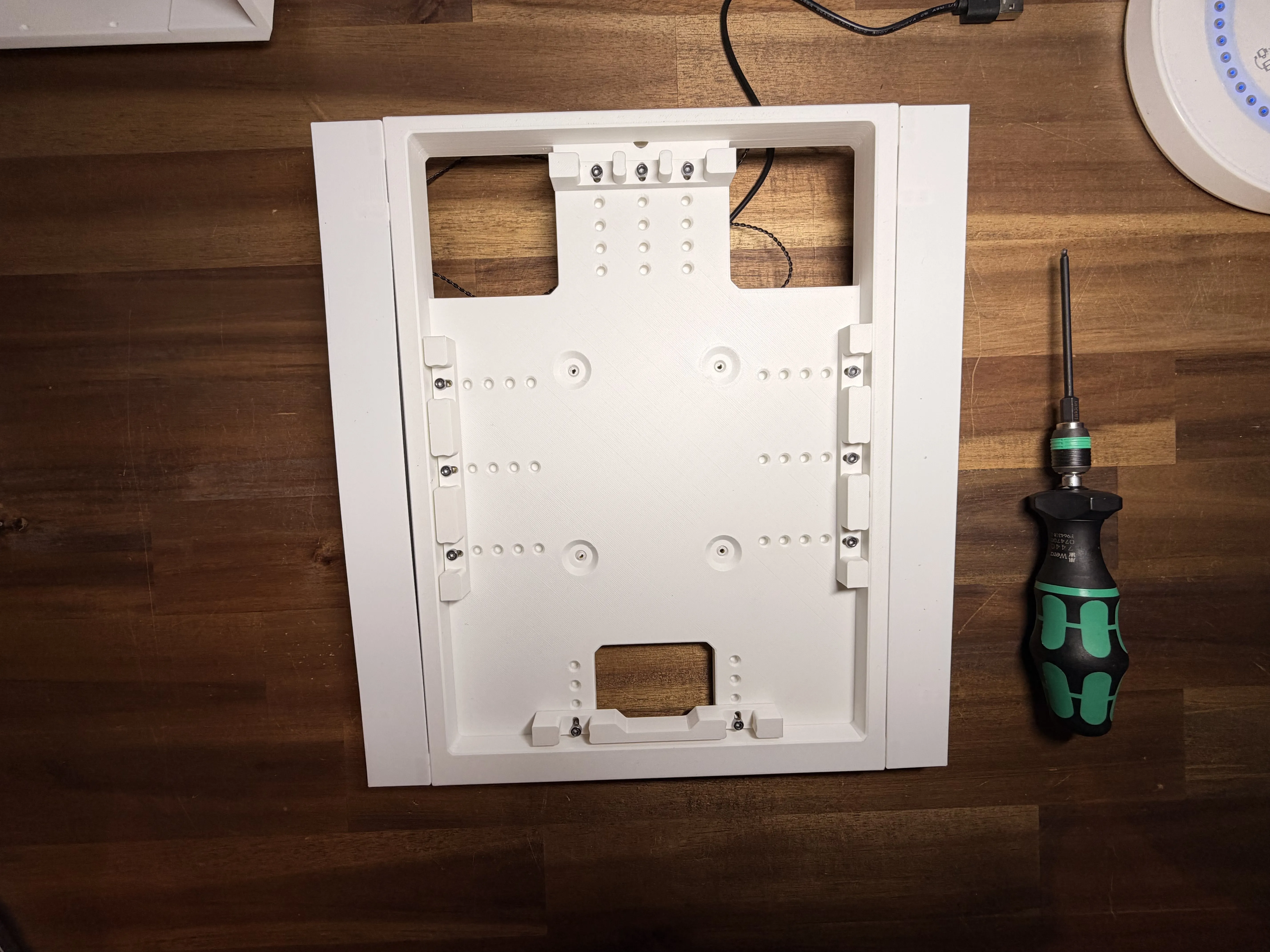
Step 9 – Installing the Threaded Inserts
Now you need to melt a total of 11 threaded inserts into the main part where everything will later be attached.
Install them in the following positions:
- 2 inserts on the left side
- 2 inserts on the right side
- 4 inserts in the middle
- 3 inserts on the top
In the picture, I marked all positions clearly for you.
The small plate in the middle was only added later because I still had a few holes from an older test version and did not want to print the whole part again haha.
So do not worry — this small plate is not included in the printable files and is not required for the build.

Step 10 – Mounting the Electronics Assembly
Now you can attach the whole electronics assembly with all the wiring onto the main part.
For mounting the main electronics section, use:
- 1x M3x8 mm screw on the top
- 2x M3x14 mm screws on the bottom
For the LED holders, use:
- 2x M3x8 mm screws for each holder
In total, you will need for this step:
- 5x M3x8 mm screws
- 2x M3x14 mm screws
Before tightening everything completely, make sure all parts are aligned properly and the cables are not trapped anywhere.


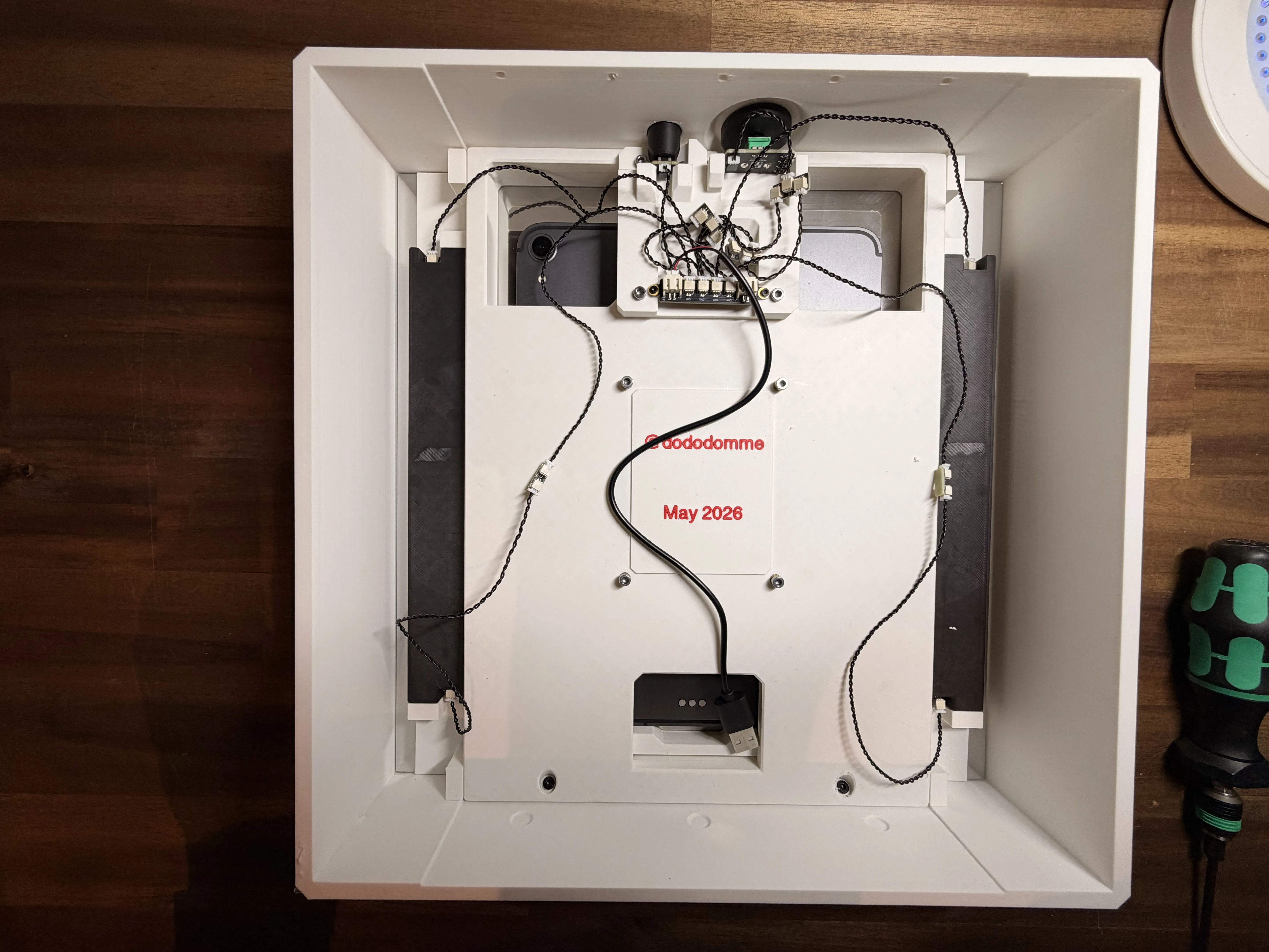
Step 11 – Current Assembly Overview
Here you can see how the assembly should look at this stage.
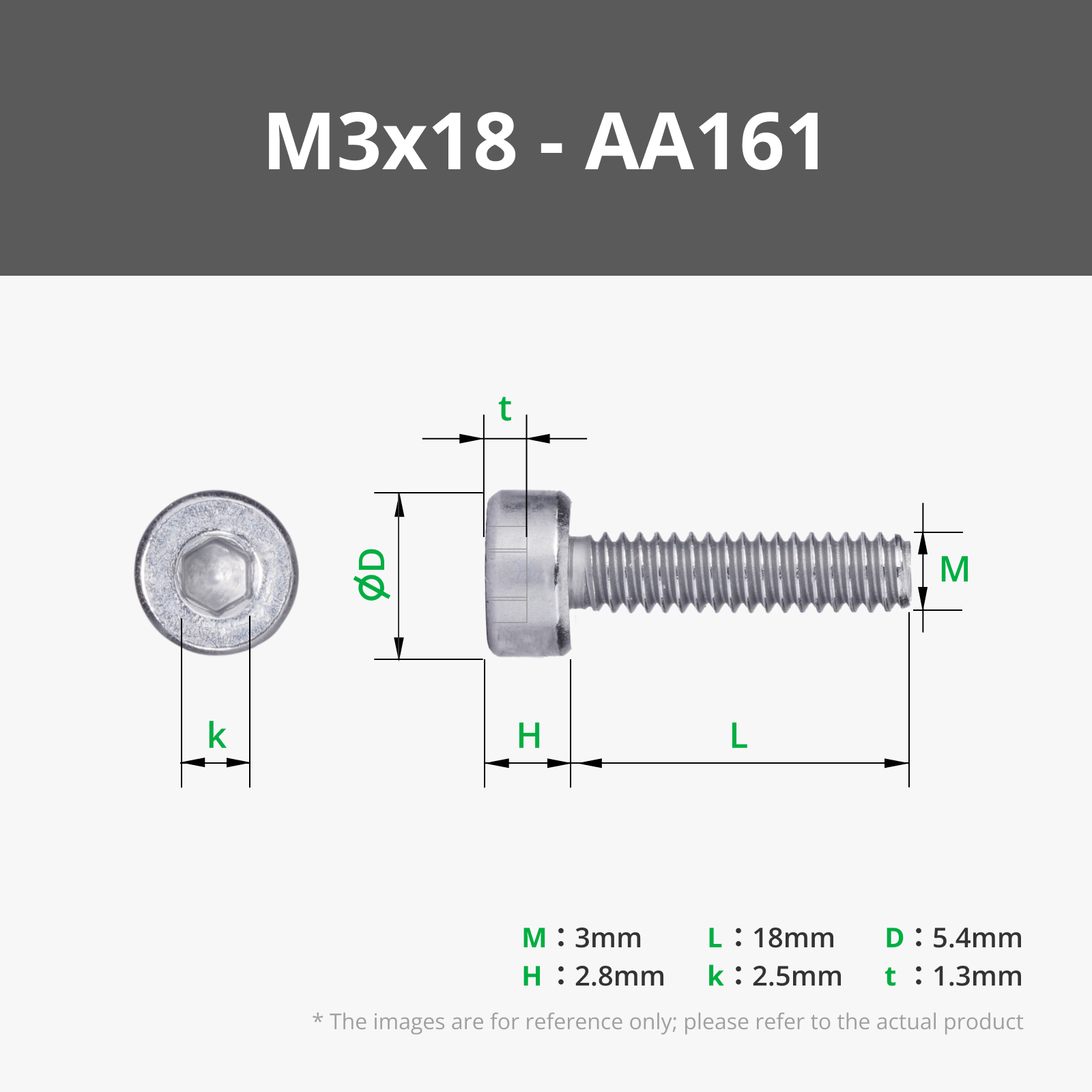
In the picture, you may notice that I already installed 4x M3x18 mm screws into the 4 threaded inserts in the middle.
Do not worry about this yet — I will explain this step in detail later because it makes more sense at a different point in the build.
You will also notice in the next pictures that these screws are removed again temporarily to make the following steps easier.
Step 12 – Applying the Mirror Film
Now comes the tricky part.
You need to apply the one-way mirror film onto the purchased 3x300x300 mm acrylic sheet.
For this, I also used a small spray bottle filled with water and a little dish soap.
If you have never done this before, I highly recommend watching a short YouTube video first, because it is much easier to understand in motion than only with pictures.
Here is the short version:
In the picture, you can see that I first cut the mirror film to about 450 mm.
I made it a little bigger than needed to give myself some extra room while applying it.

Step 13 – Applying the Film to the Acrylic Sheet
In the next step, remove the protective film from one side of the acrylic sheet.
Then spray the entire surface with plenty of water mixed with a little dish soap. It is a good idea to place a towel underneath because this can get quite wet.
Next, peel off the protective layer from the mirror film and also spray the adhesive side with the water mixture.
This makes the film much easier to position and apply without bubbles.
Now carefully place the film onto the acrylic sheet and align it properly.
Using a squeegee or scraper, slowly push all the water out from the center towards the edges until the film sits nicely on the acrylic sheet.

Step 14 – Trimming the Film
Now carefully use a knife to cut away the extra film around the edges of the acrylic sheet.
After that, let everything dry completely.
In the final assembly, I recommend placing the film side towards the inside of the SmartMirror Organizer.
The film surface is a little more sensitive, so this protects it from scratches and damage.
This way, from the outside, you will only touch the acrylic surface and not the mirror film itself.

Step 15 – Preparing the Tablet Holder
While the acrylic sheet is drying, we can continue with the tablet holder.
I designed the holder with many mounting holes and long slots so you can adjust it for both larger and smaller tablets.
I would recommend buying a simple tablet from Amazon for around 40€.
That size usually fits very well into the holder.
Unfortunately, the tablet cannot be too large because of the available space inside the SmartMirror Organizer.

Step 16 – Adjusting the Tablet Holder
Now place the tablet into the center of the holder.
Then look around all sides and check which mounting holes line up best with the holder slots.
Once you find the best positions, melt the threaded inserts into those holes.
This allows you to adjust the holder perfectly to the size of your tablet.
Step 17 – Mounting the Tablet Holders
Now lightly attach all tablet holders using M3x8 mm screws.
For this step, you will need a total of 11x M3x8 mm screws.
Do not fully tighten the screws yet.
We will adjust everything properly later once the tablet is inside the holder.
Because tablets can have different thicknesses, there is still another step coming where we will adjust the holder depth.

Step 18 – Installing the Depth Adjustment Screws
Earlier, I mentioned the 4 screws that go through the middle from the back side.
Now it is time to install them.
Insert 4x M3x18 mm screws from the back side of the part.
Then screw the 4 small round caps onto the screws from the front side.
These caps prevent the screws from touching the tablet directly and help protect it from scratches or marks.

Step 19 – Installing the Tablet
Now place the tablet into the holder and adjust all holders so they sit tightly against the tablet.
The tablet should fit securely and should not wobble later.
Do not tighten the bottom adjustment screws further yet — we will use them in the next step.
As you can see, I left a small opening at the bottom of the holder.
Most tablets have their charging port on the bottom side, so this opening allows you to connect a charging cable.
I recommend using a 90-degree angled charging cable.
These usually only stick out a few millimeters and can easily be routed towards the back side.
This way, the tablet can stay permanently connected to power.
Of course, you can also remove the tablet from time to time and charge it normally if you prefer.

Step 20 – Securing the Tablet
Now carefully turn the whole assembly around.
Make sure to hold the tablet securely so it does not fall out.
Hold the entire assembly together with your hands and slowly tighten the 4 middle screws from the back side.
The goal is to gently press the tablet forward against the front side.
This makes the tablet sit tightly against the mirror film later, which gives the SmartMirror a much cleaner and nicer final look.

When assembling the top control head, make sure the attached part is oriented correctly.
The angled sides on the bottom must face sideways. These angled areas are needed to create enough space for the mounting screws of the button.
Also pay close attention to the magnet polarity.
The magnet for the potentiometer and the magnet for the button must be installed differently:
- The potentiometer magnet should be attracted by the external magnet from the outside. This allows you to rotate the potentiometer later by turning the outer magnet.
- The button magnet should be pushed away by the external magnet. This movement presses the internal button and activates it.
So before gluing the magnets in place, always double-check the polarity orientation carefully.
The part that attaches to the potentiometer also needs to be pressed firmly onto the potentiometer shaft until the top control head sits flush with the hole on the top side.
This ensures that everything is mounted securely and does not wobble later.
The best way is to support the circuit board from underneath with one finger while gently wiggling the round magnetic part from the top as you press it into place.
Yes, this requires a bit of force — but that is intentional so the part will not loosen over time.

Step 21 – Installing the Acrylic Sheet and Tablet Assembly
As mentioned before, now insert the acrylic sheet into the frame.
I recommend placing it exactly like shown in the picture, with the mirror film facing towards the inside.
After that, carefully insert the tablet assembly behind it.
The picture below also shows a slightly easier way to fit all parts together during assembly.

Step 21.1 – Easier Assembly Position
You can also place the whole assembly almost vertically while inserting the parts.
This helps prevent the tablet from sliding out while putting everything together.
Once everything is inside correctly, place the assembly back down flat on the table so we can properly secure all parts in the next step.
Step 22 – Reattaching the Electronics Holder
Because there is not much space inside the assembly, you now need to temporarily remove the electronics holder again.
After that, reinstall it using:
- 1x M3x14 mm self-tapping screw at the top center
- 2x M3x14 mm self-tapping screws at the bottom
For this step, you will need a total of 3x M3x14 mm self-tapping screws.
Step 23 – Final Tablet Adjustment
Now screw the holder back into place.
After that, check the 4 middle adjustment screws again and make sure the tablet depth is adjusted correctly.
The tablet should sit firmly in place and press nicely against the acrylic sheet without too much force.

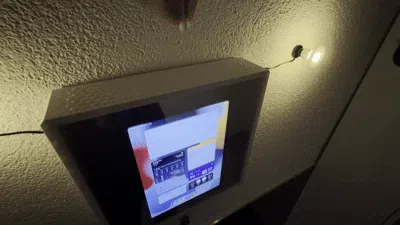
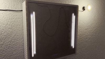
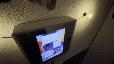
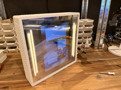
Step 24 – First Lighting Test
Here you can see how the SmartMirror looks when the tablet is turned on.
At the time of this picture, the LEDs were not set to full brightness yet, and my desk lamp was also shining directly onto the front.
The mirror effect looks much better in a darker room.
In the print profile, I changed all inner parts to black filament because, as you can see here, the LED covers slightly shine through when using white filament.
Later on the wall, I could still notice a little bit of light bleeding through, so I would recommend printing all parts inside the mirror area in black filament.
Of course, you can decide yourself which look you prefer.
It also does not look bad with white filament — it simply lets more light pass through.
The best option is probably to test both and see what you like more.


Step 25 – Installing the Wall Mount
Because I wanted to hang my SmartMirror on the wall, I designed an optional wall mount for it.
You can attach the mount using 5x M3x8 mm self-tapping screws.
Make sure the mount is installed so that the flat side is facing upwards.
If you are unsure about the correct orientation, check the next picture where you can clearly see how the mount is attached.
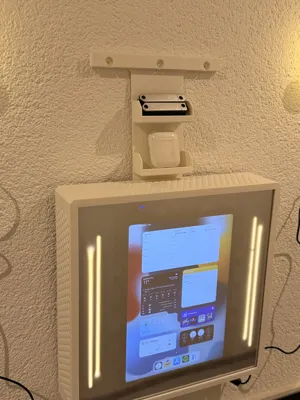
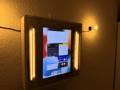
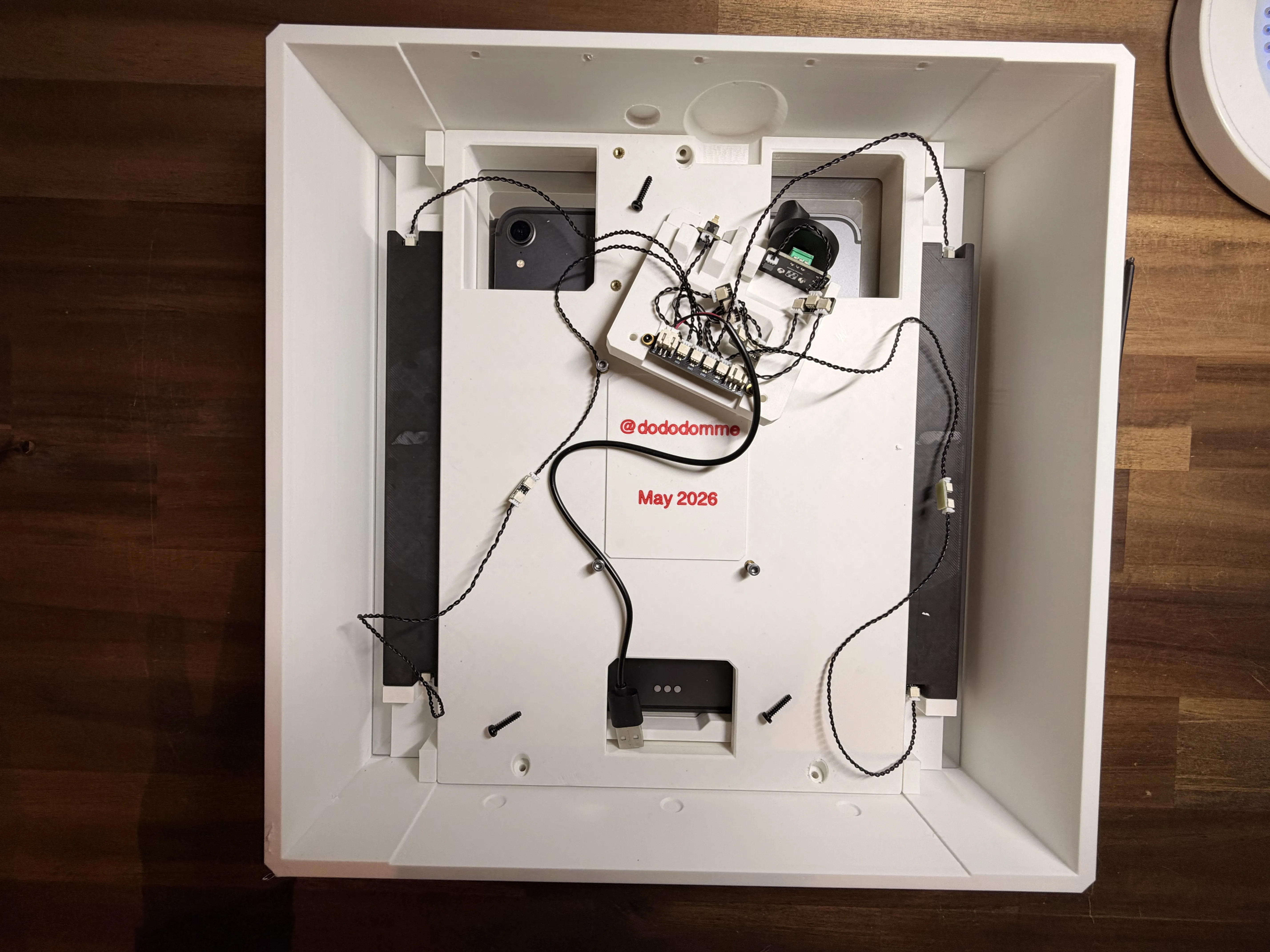
Step 26 – Mounting the SmartMirror
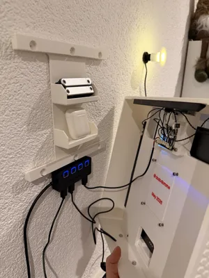
Here you can see the wall mount attached to the wall using a few nails.
I also placed a few valuable items inside the organizer to show how it can be used.
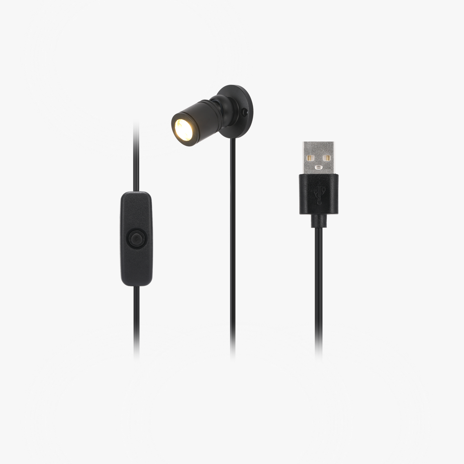
As you may notice, I mounted a small USB hub underneath the wall mount.
Once the SmartMirror is placed onto the holder, the USB ports become hidden from view.
This makes the power setup for the tablet and the LEDs look almost completely invisible and much cleaner.
Of course, the best solution would be having a power outlet directly behind the SmartMirror.
But since I live in a rental apartment, I did not want to install a new outlet haha.
With a hidden wall outlet and a flat USB hub, the final setup would probably look even cleaner.
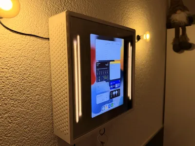
In this picture, I also connected 2 additional LED lights from Bambu Lab just to make everything look a little nicer.
These are not part of the actual project.
However, I still included the LED covers in the print profile in case someone wants to add them as well haha.

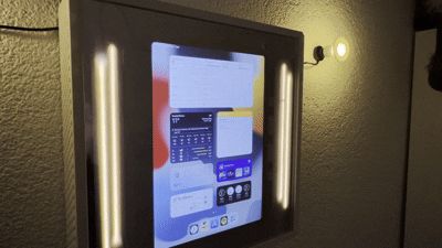
Finished – Your SmartMirror Organizer
And just like that, your SmartMirror Organizer is finished!
In my setup, I can use voice commands like:
- “Hey Siri, open the home screen”
- “Hey Siri, open my calendar”
- “Hey Siri, open Spotify”
This allows the tablet to open apps completely hands-free and makes the mirror feel even more futuristic.
I would recommend setting the tablet to automatically lock itself after about 2 minutes.
But of course, you can also leave the display always on if you prefer.
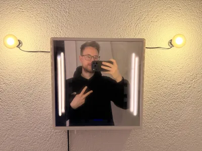
When the screen is turned off, the whole setup simply looks like a normal mirror — while secretly hiding your valuables behind it.


Hey haha
Final Details
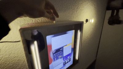
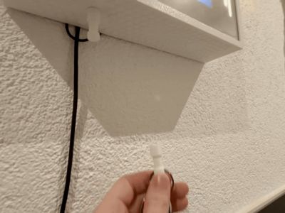
Inside the small round printed part, you can insert up to 3 magnets.
You can use this magnetic piece to turn the lights on, adjust the brightness at the top, or simply hang it underneath as a holder for your keys.
Thank you all so much, and have fun building your own SmartMirror Organizer!
Boost Me (for free)
Thank you
License
You may create derivative works based on this object, provided that all such derivative works are published exclusively on the MakerWorld platform and include proper attribution to the original creator. You may not share, upload, host, distribute, or publish this object—or any derivative work of this object—on any other digital platform, marketplace, or distribution channel. Commercial use of this object and any derivative works is strictly prohibited. This includes, but is not limited to, selling, renting, sublicensing, or using the object in any context in which you receive monetary compensation or other financial benefits.
Comment & Rating (1)