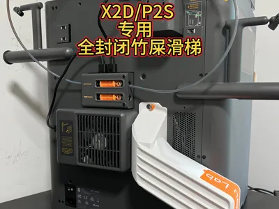
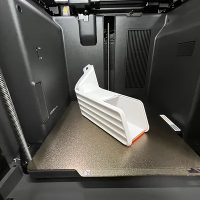
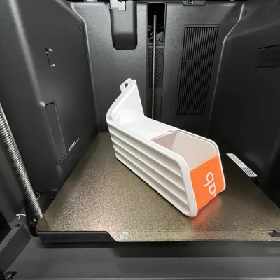
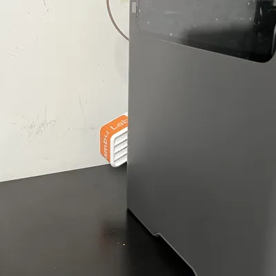
X2D/P2S Dedicated Poop Chute Waste Bin Fully Enclosed Insulated Waste Collection Roller Shutter Lid V2


Print Profile(5)


Description
Boost Me (for free)
Modeling is not easy
Boost me
It is recommended to print the main body of this model with high-temperature resistant materials like PETG, ABS, etc. PETG is recommended for the roller shutter cover
Otherwise, when printing in chamber temperature mode, the backplate will deform the chute
Installation requirements
Two files are separated: one for the main body and buckle shim, and one for the roller shutter cover. Patterns for the cover will be updated periodically, please stay tuned
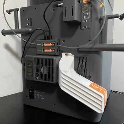
Two BT3*10 or BT3*12 flat-head self-tapping screws are ideal (screw head thickness must not exceed 1.9mm, refer to Figure 1 for dimensions). If unavailable, you can use the BT3*16 screws that secure the AMS when unboxing the AMS combo kit (I use them myself, refer to Figure 2). The three buckles have different lengths and should be installed according to the picture. The shim can be added at position C; it's optional, but adding it will facilitate quick installation. The black A screw is the original BT3*6 screw from the poop chute exit. Place the buckle on it and install it into the reserved screw hole near the cooling vent
Figure 1

Figure 2

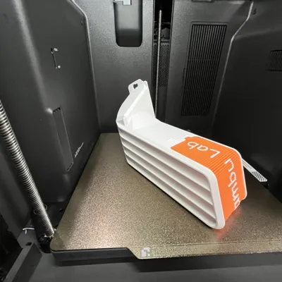
2. Printing precautions
It is recommended to print with PETG. Drying the filament and leveling the first layer are very important
The first layer height of the roller shutter should be 0.1mm
The direction of the first layer infill and the model must be correct, otherwise it will be very stiff (refer to Figure 1)
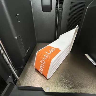
The direction of the second layer is also important, otherwise there will be air leakage (refer to Figure 2)
Figure 1

Figure 2

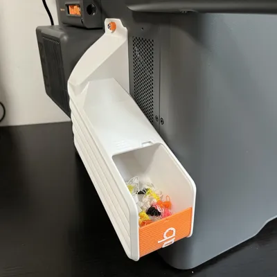
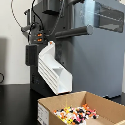
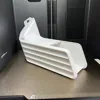
3. Roller shutter cover installation
It might be a bit stiff to install right after printing
Apply lubricant. It's not critical to apply lubricant to the edge of the roller shutter; just squeeze a small amount onto the curved sections of the track
Installation as shown

Apply lubricant as shown

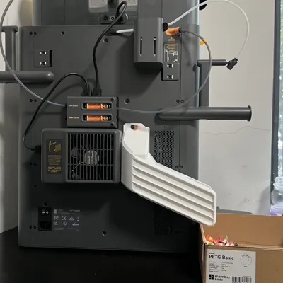
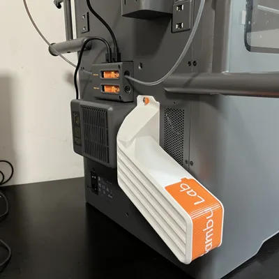
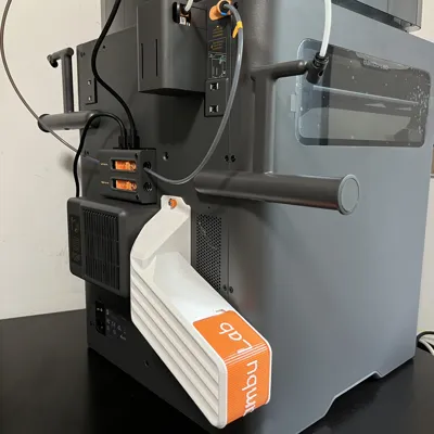
3. On-machine installation
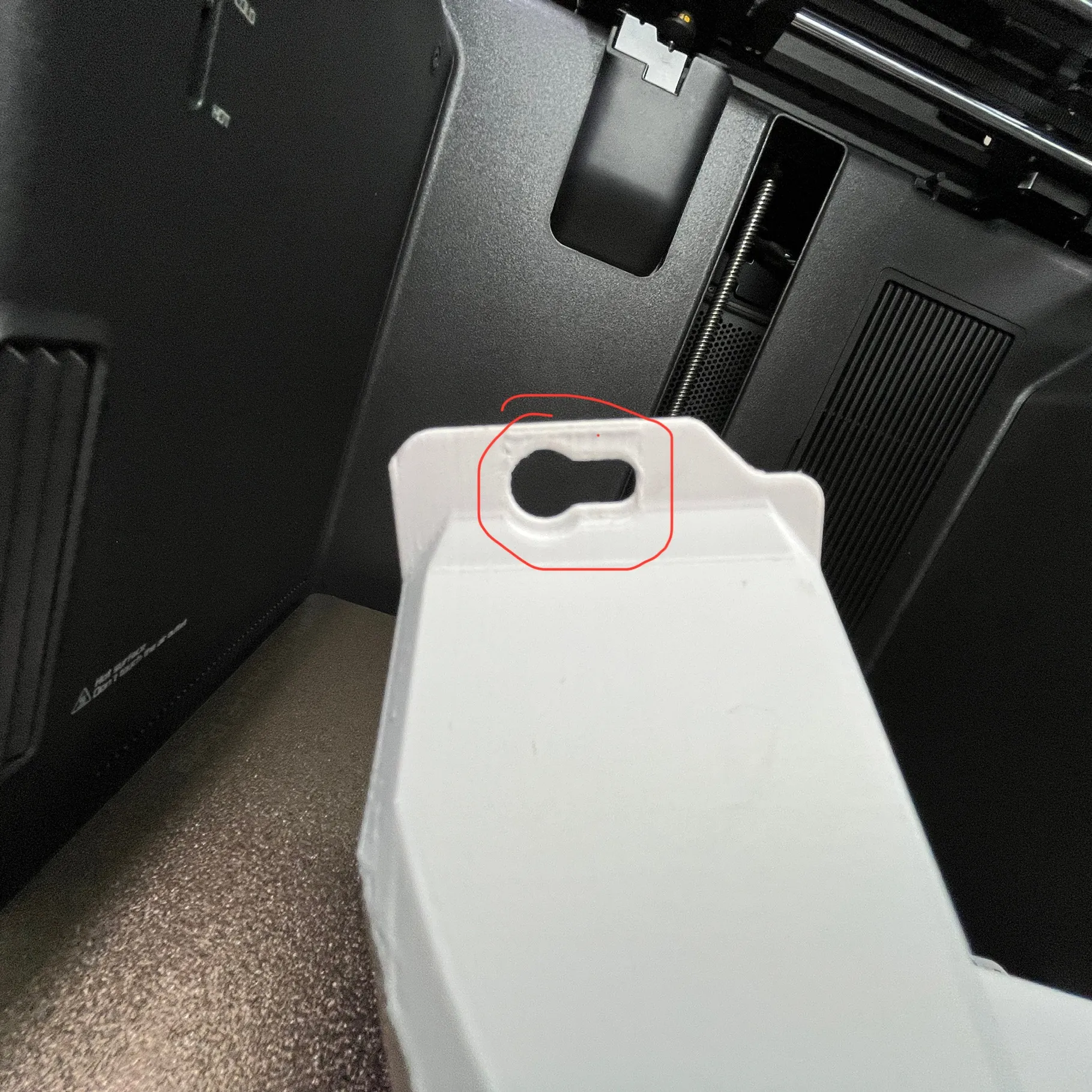
First, sand down the seams from printing the model; gently scrape them smooth with a small knife. Do not overdo it
Sanding locations are shown in the red circles below

On-machine installation steps
First, fasten the top screws, then gently and slowly snap into the bottom screw holes. Once the chute fully fits the backplate, push it towards the outer exhaust direction. Installation is complete when it is flush with the outer exhaust
Installation as shown
1

2

3

License
You shall not share, sub-license, sell, rent, host, transfer, or distribute in any way the digital or 3D printed versions of this object, nor any other derivative work of this object in its digital or physical format (including - but not limited to - remixes of this object, and hosting on other digital platforms). The objects may not be used without permission in any way whatsoever in which you charge money, or collect fees.
Comment & Rating (2)