MP Rotator (Dis)Assembly Tool


Print Profile(1)
Description
Description
This model is a disassembly and assembly tool for Hunter irrigation valves of the MP Rotator series (MP 800, MP 1000, MP 2000, MP 3000, MP LS/RS/SS).
Background:
I operate a lawn irrigation system with Hunter irrigation valves. Some valves occasionally stopped running smoothly after some time. They stopped rotating and only sprayed in one direction. On Youtube, there's a video (https://www.youtube.com/watch?v=LblNpvx7Hos) that shows how to fix this problem. You disassemble the rotator and re-grease it. This tool was created for disassembling and reassembling it.
Parts
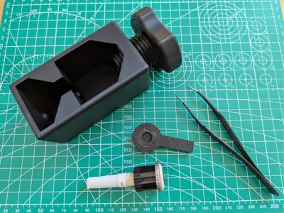
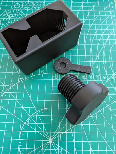
The tool consists of 3 parts.
- The Body: Holds the rotator.
- The Piston: Used to disassemble and re-press the rotator.
- The Supporter: Is used in different positions depending on the operation.
- Open

- Assembly

- Open
Assembly
- I printed the 3 parts with Sunlu PLA+ 2.0 in black.
- For printing the support component, I additionally used “Support for PLA”.
- After printing, remove the support filament from the support component so that a curve is formed.
- Apply a little grease to the thread between the body and the piston.
Instructions
Disassembly / Opening the Rotator
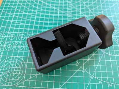
The rotator is placed onto the supporter.

The supporter with the rotator is placed into the body.

- The piston is slowly turned down. Once the piston makes contact with the rotator, turn it about a quarter to half a turn further.

- The rotator's “lid” is pressed open and can be removed.

- The rotator is disassembled and open. You can now begin greasing the rotator.

Assembly / Closing / Pressing the Rotator
- The rotator's “lid” is placed on.

- The rotator is placed into the body. The lower end of the rotator is pushed through the bottom of the body. The rotator rests with its housing in the middle section of the body.

- The supporter is held between the rotator and the piston, and the piston is slowly turned down until there is contact between the piston, supporter, and rotator. Note the orientation of the supporter, see schematic drawing: The supporter is now used the other way around, compared to disassembly. Then, very gently, turn it a quarter to half a turn. This will press the rotator with the lid.

- Loosen the piston and remove the rotator

CAUTION
- DO NOT apply excessive force to the rotator.
- If the white foot of the rotator bends when opening it, too much pressure has been applied to the rotator! Please only apply ¼ to ½ turn of pressure to the rotator.
License
You shall not share, sub-license, sell, rent, host, transfer, or distribute in any way the digital or 3D printed versions of this object, nor any other derivative work of this object in its digital or physical format (including - but not limited to - remixes of this object, and hosting on other digital platforms). The objects may not be used without permission in any way whatsoever in which you charge money, or collect fees.
Comment & Rating (3)