Wooden Train John Street Roundhouse, Toronto V1


Print Profile(3)
Bill of Materials


- https://www.amazon.com/Dowellife-Resistant-Protection-Shucking-Processing/dp/B06XBGR2L9 x 1: Kelvar Cut Resistant Gloves
Description
Overview
This roundhouse is modeled after the Toronto Canada, historic John Street Roundhouse. Built in 1929 by the Canadian Pacific railroad to service steam locomotives, the 32-stall roundhouse was closed in 1982. It has been flagged as a National Historic Site of Canada and is currently being rehabilitated for alternate uses, which will ensure future public access.
Figure 1: Toronto John Street Roundhouse

This is a 5 stall version of the John Street Roundhouse that is compatible with Brio, Thomas, Sainsmart and Ikea wooden train systems. A gear driven Turntable is also included.
More information about the John Street Roundhouse can be found here:
https://www.pc.gc.ca/apps/dfhd/page_nhs_eng.aspx?id=544
I took some artistic license with the roundhouse is stretched vertically to accommodate the Wooden Train scale. The windows are green to add some contrast. And I added windows to bay doors plate 11, however I included solid doors that are similar to the original doors on plate 12. Only print one of the 2 plates.
Parts list
Here are the only parts that I used.
3 – M3x8mm Flat Head Screws.
Assembly
The following illustrations walk through the assembly process for the Roundhouse.
Note: It is always a good idea to test the fit of any parts before gluing.
Typically any fit issues can be taken care of by scraping or cutting a part with a razor knife. Be careful and hold the parts in way that if the blade slips, it will not cut you, or wear Kelvar Cut Resistant Gloves. See the Other Parts in the Bill of Materials.
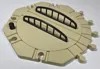
Base Assembly
Align the dog bone lock slots on the Round House Base Center and Left and press the dog bones/Locks into them (as indicated by the yellow arrows in Figure 2). It may be necessary to put the parts face up, on the corner of a strong table and use your shoulder to press the locks in so they are flush to the bottom of the Base.
Figure 2: Base Center and Left Assembly

Align the dog bone lock slots on the Round House Base Center and Right parts and press the Locks into them (as indicated by the yellow arrows in Figure 3).
Figure 3: Base Center and Left Assembly

Roof Braces to Base Assembly
Take the 4 Roof Brace Assemblies, and the Roof Brace Left and Right parts and the assembled Base and assemble them as follows.
Individually take each Roof Brace and press it in to the appropriate holes in the Base, as illustrated by Figure 4. Place the base on a table and holding onto the Roof Brace rear vertical beam, press it into the rear hole in the Base. Then press the front vertical beam into its associated hole in the base (as shown by the green arrows). When properly inserted, the bottom of the Roof Brace vertical beams should be flush with the bottom of the Base.
Note: Use your shoulder to press the two parts together. It takes a lot of force, but they do not need to be glued.
Note: Be careful to press the parts straight in. If you slip off to the side you may break a Brace.
Figure 4: Roof Bracket and Roof Brace Assembly

Window Assembly
The following procedure should be followed for attaching all the windows and doors. Note that the bottom of each window slot on its backside is chamfered to help it fit in place (see Figure 5).
Note: Except for the Upper Side Windows, the tops of all the windows are thicker than the bottoms. Be sure that the windows are in the correct orientation when inserted (see Figure 5).
- For the left and right walls, place the wall on a flat surface with the bricks facing down.
For the Roof Windows, since the Window Frame is curved, you need to hand fit the Windows (Top Window 12 over 12). - At about a 30 degree angle, press the top of the windows (or door) into the Wall with the top of the window flush with the back of the wall and the top of the window slot (yellow arrow in Figure 5).
- Then swing the bottom of the window against the chamfer at the bottom of the window slot (green arrow).
- Finally turn over the wall on a hard, flat surface and press the wall against the window until its back is flush with the back of the Wall, as illustrated in Figure 6.
- Finally run a bead of glue around the inside of the joint between the window and the wall, to hold them together.
Figure 5: Window Fitting A

Figure 6: Window Fitting B

Now work your way through all the windows on both walls, and the Roof Windows.
Figure 7: Side Window Assembly

The 14 Roof Windows (Top Window 12 over 12.stl) are inserted from the back of the Top Window Frame, using the same method as for the Wall Windows, as described above.
Figure 8: Roof Window Assembly

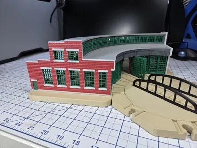
Wall Assembly
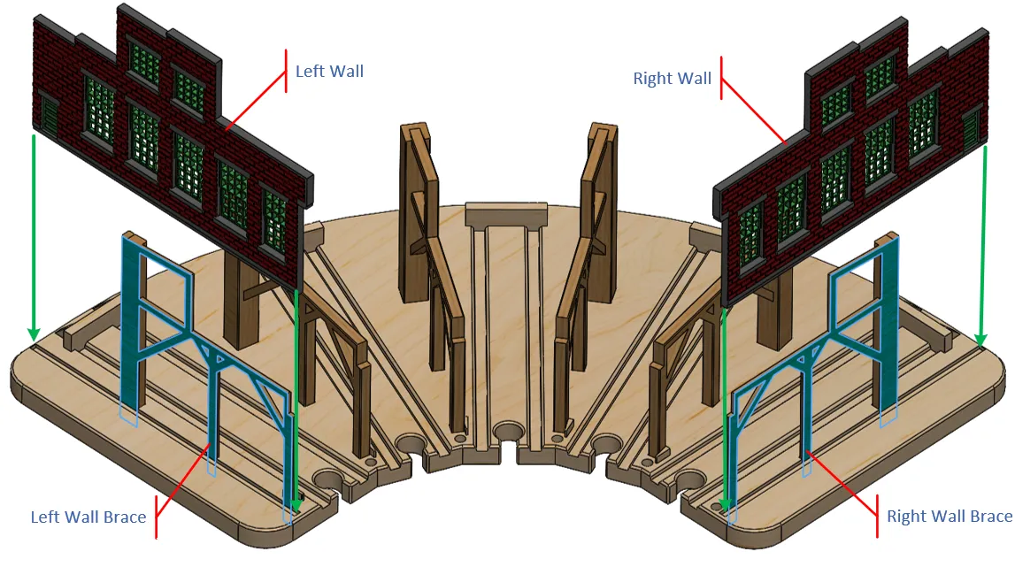
Run a bead of glue along the bottom edge of the Wall Assemblies and on the outside edges of the Right and Left Wall Braces (blue surfaces), press the Wall into the Base tilted away from the Wall Braces (to avoid disturbing the glue on the Wall Brace), the tilt the wall flush against the Wall Brace, and hold it until the glue cures.
Note: Make sure that the walls/braces are vertical!
Figure 9: Wall Assembly
Door and Lower Front Roof Assembly
Note that there are 2 Roundhouse Door options; with or without windows. The windowed doors are on Plate 11 and the solid doors (like on the John Street Roundhouse) are on Plate 12. Figure 19 shows the design with the windowed Roundhouse Doors and Figure 29 shows the design with the solid Roundhouse Doors.
Insert the bottom hinge pin of the 5 Roundhouse Doors into their respective holes as shown by the green arrows in Figure 11.
Put glue on the end surfaces of the Inner Wall Top (blue outlines in Figure 11) and on all the Wall Brace surfaces (blue lines in Figure 10).
Figure 10: Inner Wall Glue Spots

Then press the Inner Wall Top part down on top of the door hinges, aligning the upper door hinge pins into their respective holes in the Inner Wall (Figure 11).
Figure 11: Roundhouse Doors and Inner Wall Top Assembly

When the Inner Wall Top part is properly positioned it should look as shown in Figure 10.
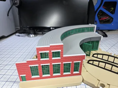
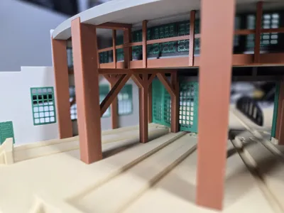
Balcony Assembly
There is a balcony behind the Upper Windows. Put glue on the end surfaces of the Gallery Balcony and on all the Wall Brace surfaces (blue outlines in Figure 12).
Then slide the Gallery Balcony down the Wall Braces until the bottom of the Balcony is flush with the top of the Wall Braces.
Figure 12: Balcony Assembly

Railing Assembly
There are 5 railing parts: 3 Center, a Right and Left. Apply glue to the bottoms of the posts and the end of the railings, as shown by the blue lines in Figure 13.
Figure 13: Front Roof Gluing

Wall Post Assembly
Put a bead of glue on the face of the Wall Post part (as indicated by the blue line in Figure 14 A). Then press the Wall Post into position as shown in Figure 14 B.
Figure 14: Wall Post Assembly

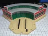
Lower Roof Assembly
Put glue on the surfaces outlined by the blue lines in Figure 15, then press the Lower Roof onto the glue covered Roof Brace surfaces. The front lower edge of the Lower Roof should be flush with the Inner Wall Top.
Figure 15: Lower Roof Assembly

Roof Window Assembly
Put glue on the ends of the Roof Window Assembly and across its bottom, as indicated by the blue lines in Figure 16. Then press it into the grove on Front Lower Roof.
Figure 16: Roof Window Assembly

Upper Roof Assembly
Put glue on the surfaces marked in blue in Figure 17 and press the Right and Left Roof Upper parts together (green arrows in Figure 17). Then press the 3.5mm dog bone (Lock Lock V1 3.5mm) parts into their respective slots (yellow arrows). The dog bones should be flush with their respective surfaces.
Place the roof on a flat surface until the glue cures.
It may be necessary to put the parts on the corner of a strong table and use your shoulder to press the locks in so they are flush to the bottom of the Upper Roof parts.
Figure 17: Upper Roof Assembly Part A

Put glue on the ends of the Roof Upper Assembly in Figure 18 and the tops of the Roof Braces and Railing posts (indicated in blue).
Now press the Upper Roof onto the Roof Braces, making sure that the Braces align with their associated slots in the Roof.
Figure 18: Upper Roof Assembly Part B

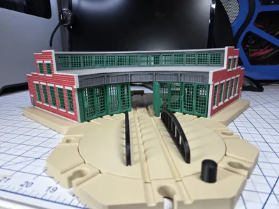
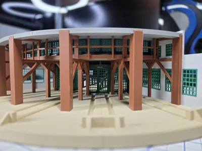
Completion
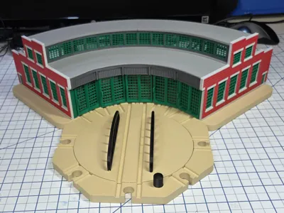
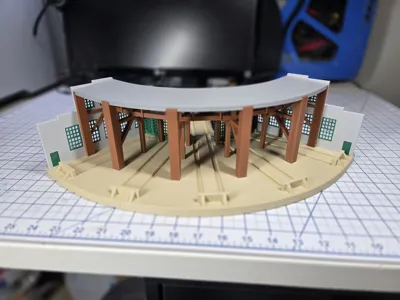
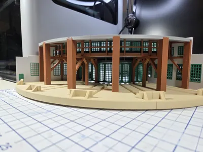
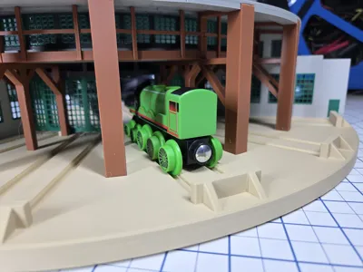
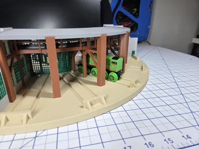
When the Roundhouse is complete, add the accessories, and you are ready to go. See Figure 19 and Figure 20.
Figure 19: Roundhouse Front View

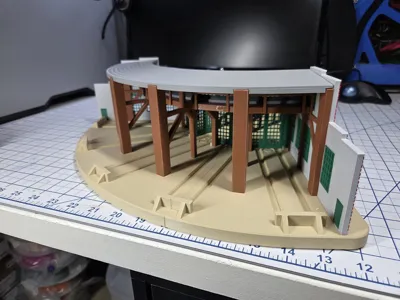
Figure 20: Roundhouse Rear View
Optionally you can install the Stall IDs. These are simply glued to the Inner Wall Top, centered in each panel.
Figure 21: Stall IDs

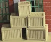
Accessories
A number of accessories are included with this design.
The Coal Bin has a slot in it which allows the shovel to be inserted, however the shovel may be used independently.
Note that the accessories are not to scale. Any smaller they would start loosing detail.
Figure 22: Crates and Coal Bin, and Shovel

Figure 23: Bucket and Wooden Barrels

Figure 24: Steel Barrels

Turntable Assembly
The turntable mates with the Roundhouse to prove access to the 5 Roundhouse engine bays.
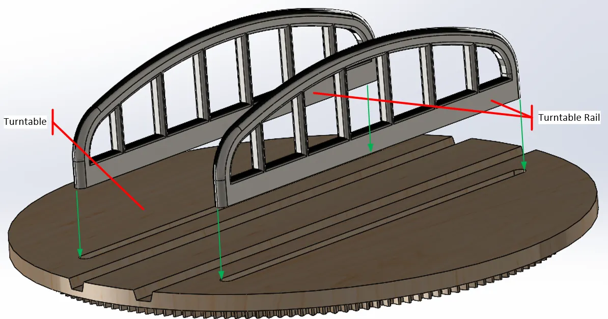
Install the 2 Turntable Rail parts by running a bead of glue along their bottom edge and pressing them into the Turntable part.
Figure 25: Turntable Rails
From the bottom of the Turntable Base, drop the Turntable Drive M1 T33 gear into the hole, position the Turntable Drive Gear Cover over the gear, then use 2 M3x8mm Flat Head screws to attach the Cover to the Base. When complete the Cover and screws should be flush with the bottom of the Turntable Base.
Figure 26: Turntable Drive Gear

From the top of the Turntable Base insert the Turntable, then turn the assembly over and secure the Turntable Cap to the Turntable as illustrated in Figure 27.
Figure 27: Turntable Attachment

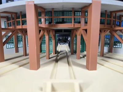
Figure 28: Final Assembly with Turntable

Plates
Plate 1 – Base Left and Base Dog Bones – PLA Matte Desert Tan.
Plate 2 – Base Center – PLA Matte Desert Tan.
Plate 3 – Base Right – PLA Matte Desert Tan.
Plate 4 – Walls – Light Gray (motar) and PLA Matte Dark Red (bricks).
Plate 5 – Roof Braces Main – PLA Brown and PETG interface material to provide clean surfaces.
Plate 6 – Roof Braces Right and Left, Balcony, and Railings – PLA Brown.
Plate 7 – Roof Window Frame and Inner Wall Top – PLA Dark Gray.
Plate 8 – Upper Roof and Roof Dog Bones – PLA Gray.
Plate 9 – Lower Roof – PLA Gray.
Plate 10 – Windows, Side Doors and Post – PLA Bambu Green.
Plate 11 – Doors with Windows – PLA Bambu Green. Do not print of printing Plate 12.
Plate 12 – Doors without Windows – PLA Bambu Green. Do not print of printing Plate 11.
As much as possible I tried to design the parts to minimize or eliminate support requirements.
Plate 4 is a 2 color print, but generally the Plates are organized by color.
Plates 5 and 8 use PETG as an interface material to provide clean bottom surfaces on the Roof Braces and Upper Roof. It takes longer, but it really helps to ease the removing the support material and providing a better fit of the parts.
For the prototype I printed the Plates that used 2 filaments on an H2D because it was faster, the rest were printed on a P2S. The Print Profile is configured for a P1S, but you can change the printer to any printer that has a bed size of at least a 256x256m.
If you change the printer from the P1S default, check the position of the Purge Towers on Plates 4, 5, and 8. Studio has a habit of moving these around when another printer type is selected. The rest of the parts are typically in correct positions.
Revision information
5/4/26 V1 – Initial release.
5/10/26 V1a - Added print profiles for Turntable and Accessories.
Comment & Rating (3)