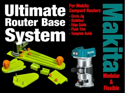
Makita - Ultimate Router Bases System


Print Profile(1)

Description
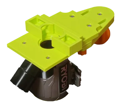
This is a complete flexible router base system for the Makita compact palm router (Model #RT0700).
I also have a Ryobi and Bosch version. Check out my other models here: https://makerworld.com/en/@user_3482586536/upload
Boost Me (for free)
I'd appreciate your Boost. A lot of effort goes into this kind of model and boosts motivate me to make more stuff.
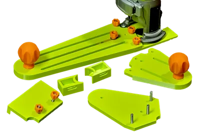
You get the following:
- Base plate that is guide bushing ready (you need standard brass guide bushings and bushing nut)
- Stabilizer (for easier routing, you could also call this an extended base)
- Edge Guide (up to 175mm)
- Flush trimming
- Circle Cutting (from 60mm to 230mm radius)
- Extra Long (XL) Circle Cutting (up to 360mm radius)
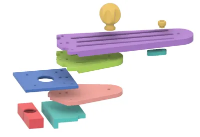
It includes one of each of these main parts:
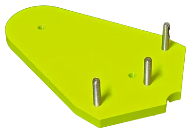
- Router Base plate (Screws onto router and replaces the existing base)
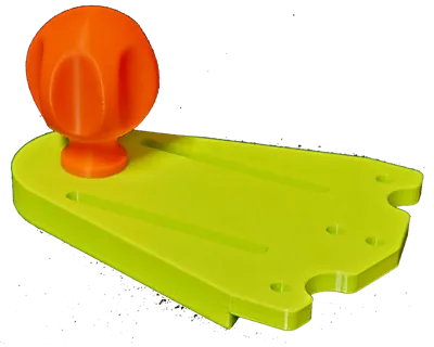
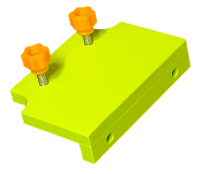
- Stabilizer Plate (can also be used with the edge guide for shorter distances)
- Flush trim plate
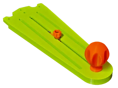
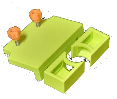
- Circle Guide (regular + XL) / Edge Guide Plate (use with the circle pivot for making circles or with the Edge Guide for a longer edge guide)
- Circle Pivot used with the Circle Guide as the pivot for making circles.
- Edge Guide Plate (used on the Stabilizer or Circle Guide as-is or preferably, screw a piece of wood to it)
- Edge Guide Attachments for trim and bevel routing.
- Knobs (a Large Knob (print two) and Thumb Knobs (print 6) to connect the parts)
Hardware Required:
This system is mostly based on M5 Button Head Cap Screw bolts. One M3 and nut is also required for the Circle Pivot. You can find both on Amazon or Aliexpress. My apologies to those of you who prefer imperial hardware.
- Existing base screws from your router
- 7x M5 button head bolt 20 mm (one for each of the two Large Knobs, three for connecting Stabilizer Plate and Circle/Edge Plates to the Base and two for connecting the Edge Guide Attachments to the Edge Guide Plate)
- 5x M5 button head bolt 25 mm (for connecting the Flush Plate and the Edge Guide Plate - these are longer because they have to also go through the Stabilizer or Circle/Edge plates. These are a tight fit and are meant to be left on the respective plates)
- 1x M5 button head bolt 16 mm (for the circle pivot)
- 8x M5 hex nuts (Used in the Thumb Knobs, the Edge Guide Attachments and Circle Pivot)
- 6x M5 washers (preferred but not critical for connecting the plates: Circle Pivot, Edge Guide, Edge Guide Attachments. No washers are needed for the large knob)
- 1x M3 hex cap head bolt 15 mm (for the Circle Pivot, goes nicely into a 1/8" pivot hole)
- 1x M3 hex nut (for the Circle Pivot)
- Optional 2x #8 pan head wood screws to attach a wooden face to the edge guide if desired.
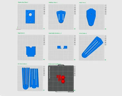
Printing
All parts are oriented for printing.
I printed all plates in PETG except the Knob, thumb knob and circle guide which are in PLA. You can use either or both, your preference. You should be aware that PLA is stiffer and probably a better choice as a result.
No supports are needed except for the Edge Guide Attachments, depending on how good your bridging is.
If you want a better face on the Edge Guide Attachments, re-orient to print with the face down - but if you do, you will certainly need supports.
If you want a smoother top surface on the Large Knob, move it to a plate by itself and use variable line height.
They are fine for me as-is, but If you want the plates stiffer, print in pla, increase the infill to 25% and set the top and bottom layers to 6. This will take more material and time to print.
Assembly
Remove the existing base plate from the router and screw on the new base plate. You can orient the plate either direction, I have the plate attachment holes on the side of the depth adjustment mechanism.
Use the M5 bolts, washer and thumb knobs to attach the various plates. There are 3 knobs, but you can likely get away with only 2 knobs except for when you attach the flush trim plate.
For the large knob, the hole is not threaded, it is undersized so you can screw an M5 bolt directly into it.
For the thumb knobs, push the nut into the top until it bottoms out. It should be a snug fit.
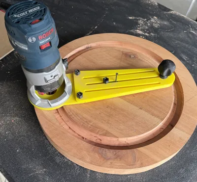
Circle Guide
Attach the Circle Guide / Edge Guide Plate to the router base with three 20mm M5 bolts, two washers and three thumb knobs. (you could use only two bolts if preferred.)
There is also an Extra Long version. The XL version is in two parts with a dovetail connector. Press fit or glue these together for a much larger circle cutting capacity. Attach to the base plate the same way.
For the Circle Pivot, add the m3 nut in the hex hole on the bottom and screw the M3 bolt in from the top and tighten so that about the bolt is sticking out. This will be the pivot pin. You can adjust how much sticks out by using a different length M3 bolt.
Screw in the M5 bolt from the bottom of the Circle Pivot so that the head is in the inset. The hole is slightly undersized so that the bolt will stay in place.
Install the Circle Pivot into the center slot of the bottom of the Circle Guide / Edge Guide plate. Add an M5 washer on top and screw on a thumb knob.
Position the Circle Pivot so the M3 pivot pin is at the desired distance from the router bit. You can flip the direction of the circle pivot to reach the farthest points.
Edge Guide
Screw in three M5 25mm bolts from below. The hole is slightly undersized so the bolts will stay in place.
Attach the Edge Guide to the two slots in either the Stabilizer or the Circle Guide / Edge Guide Plate with washers and thumb knobs. Position as needed.
Optional - Using the wood screws, screw on a wood face through the provided holes. This enables you to get a wider edge face.
Optional - You can attach the Edge Guide Attachments using 20mm M5 bolts, nuts and washers. Slide them side to side and position them to reveal the amount of bit you want.
Flush Plate
The flush plate attaches to the router base with the Stabilizer Plate attached.
Screw in three 25mm M5 bolts from the bottom of the flush plate so that the head is in the inset. The hole is slightly undersized so that the bolt will stay in place.
Attach the Flush Plate to the Stabilizer plate and onto the Base with the three M5 bolts with washers and Thumb knobs on top. If the Stabilizer Plate is already installed, remove the existing bolts/Thumb Knobs first.
Design Notes
This was designed in Fusion 360. Each part is a separate component.
There were many iterations, mostly for holes and slots to get the right size.
It is designed with metric hardware because that is the easiest way.
Sorry, the Fusion file will not be released.
Any comments, suggestions welcome.
Comment & Rating (2)