R2D2 Mk4 Charge port and Data port -Printed Droid


Print Profile(1)
Description
Here is my rendition of MrBaddeley's Mk4 R2D2 Charging port and Data port. I added some more details to them and added mounting system to fit Printed Droid light boards. I will list all of them below with links to what I used.
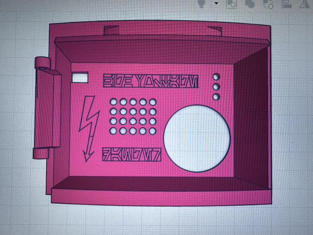
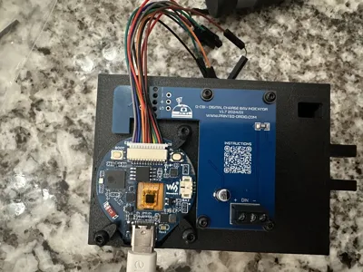
Charing Port
-Printed Droid DPL VU & D-CBI light boards https://shop.printed-droid.com/produkt/dpl-vu-d-cbi/
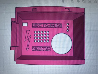
-Details added- High Voltage and Danger in aurebesh, lightening electric symbol
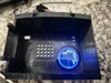
-Radar Screen- ESP 1.28" Screen https://www.amazon.com/dp/B0CSFPQDQB?ref_=ppx_hzsearch_conn_dt_b_fed_asin_title_8
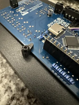
-Radar screen programed to dim when door is closed via NORMALY OPEN reed switch connected to GPIO 15 on screen (other end goes in ground pin), so when magnet is applied, the screen dims. Same style as Printed Droid dimming method.
-Screen mounted via 3 tabs using M3x8mm screws. DO NOT over tighten them as you will get screen artifacts, just tight enough to no easy move.
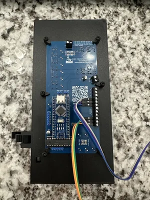
-Board mounted 4 M2x6mm screws in this stack order- 2 washers → board → 2mm printed adapter → charging port. WASHERs are important, as without them the screws go too deep and will distort visual side of the port.
-Supports needed at minimum for the screen mounting area, screw holes optional.
-Screen program in linked github below as makerworld would not let me include it. Adapted from original work of The Last Outpost Workshop https://dev.azure.com/overlording/The%20Last%20Outpost%20Workshop which will have more information about the sketch building process as well.
- https://github.com/bjwest9738/ESP32-1.28-Star-Wars-Tactical-Radar
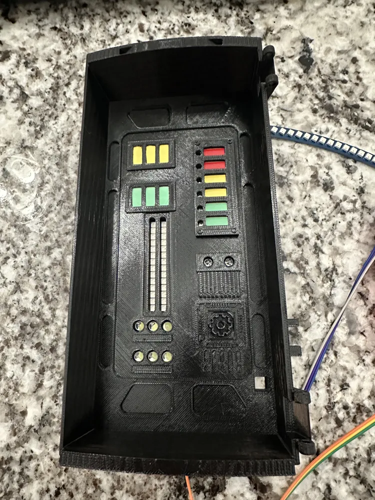
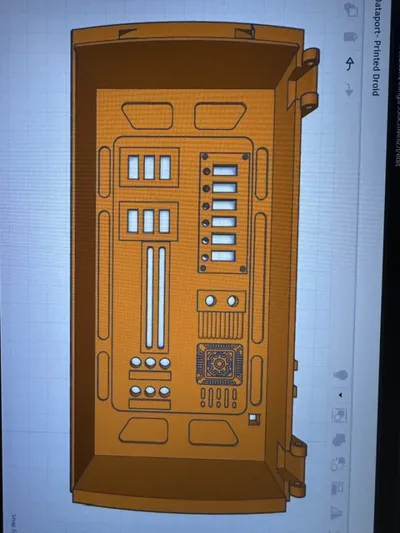
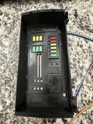
Data Port
-Printed Droid light board from kit above.
-Details added- enclosed light bars so edges not seen, recessed trim on sides, greebles on bottom right including circuitry and gear.
-Board mounted via 6 tabs using M3x10mm screws.
-Supports needed for the rectangle LED openings.
I have not altered the included code on the boards to change anything. The screen just plays the Star Wars tactical radar in a loop. More effects can be added if you desire and integrated into your droid control programming. I am not providing and code or information on this subject, just providing the basic code that can be flashed to ESP screen via Arduino IDE.
Bill of Materials
-Printed droid boards
-ESP32 S3 1.28" Screen
-3x M3x8mm screws
-4x M2x6mm screws
-8x M2 washer
-6x M2x10mm screws
Comment & Rating (2)