Modular ATX Lab Bench Power Supply


Print Profile(1)
Description
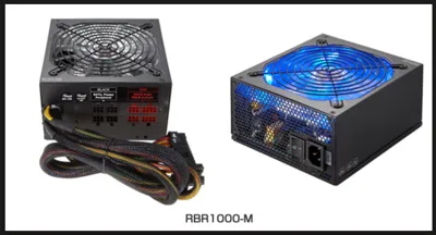
I love the power supply that Caelestis Workshop posted: Upcycled ATX Lab Bench Power Supply - Free 3D Print Model - MakerWorld, however, all my old PSUs were the modular style, specifically a Rosewill RBR-1000-M. These are slightly larger, about 10mm longer, enter the remix! All printed in PETG to give added heat resistance. I also modified the faceplate to fit my selected parts below, the name plate to make it a bit taller, and the housing to print it without supports.
⚠️ SAFETY WARNING: High-wattage power supplies like this Rosewill contain large primary capacitors that can hold a lethal DC charge long after the unit is unplugged. Even if the unit has been sitting, always verify they are discharged with a multimeter before touching the internal PCB. Never work alone on high-voltage equipment. If you are unsure of how to safely discharge a PSU, please research "capacitor discharge bridge" or consult an expert before proceeding. ⚠️
Caelestis Workshop made a great Instuctable Page for this, please review that before you continue here. I did some things slightly different which I cover below, but their page is a great base reference to work with!!!
All the supplies linked in the original are from AliExpress and about half go to 404 errors, so here are the supplies I ordered via Amazon:
- Banana Plugs
- Power Button: pick the color you like, blue matched the fan color of my PSU!
- Buck Booster Supply
- USB Small Version: This is a smaller size than most - you may have to make the hole bigger if you use something different
- Fuses and Holders: E279 option
- Terminal Block: 6 terminal 15A
- Threaded Inserts: M3
With the “newer” power supplies, no resistor is required, as they will run just fine unloaded, the original used one, I did not.
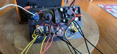
Remove the PSU cover, mine was held in place by 4 screws on the top, when removing, pay attention to the power cord going to the fan, you will have to unplug this to fully remove the cover.
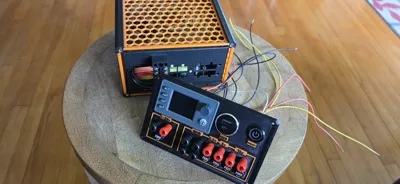
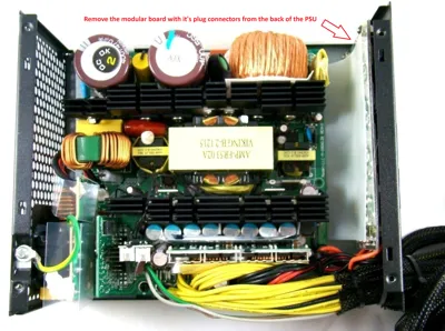
Remove the modular plugs from the back of the power supply, mine had a separate board that was held in place with 5 screws. I removed the screws, pulled the board with all the plugs, and snipped the power going to the modular board and taped off any open wires. If you have access, snip as close to the main board as possible so you don't have to tape off the wires, it makes for a cleaner finish. Then I cleaned up all the other wires going out the back of the power supply, I kept only the wires I needed. My supply had 18ga wires which can safely carry about 10 amps, so as an overabundance of caution, I kept enough to carry 40 amps. I saved 4 of each voltage and 8 grounds, all spread evenly between different terminals on the main board.
When cleaning up the wires keep the following:
- Small Green Wire: Power Switch
- 8 black wires: these are your grounds (-)
- 4 yellow wires: +12V
- 4 red wires: +5V
- 4 orange wires: +3V
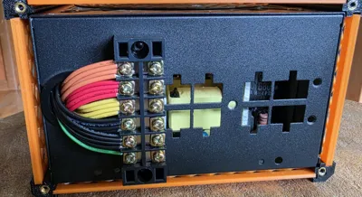
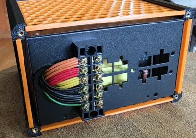
Using the Terminal Block, position it on the back of the PSU and mark the locations for 2 holes to be drilled. You will drill these holes carefully, ensuring not to push through and catch anything inside the PSU. I put a paper towel inside my PSU while drilling to prevent any metal shavings from getting in the electronics. Once drilled, use M3 screws, washers, and nuts to mount your terminal block to the PSU.
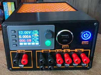
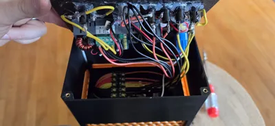
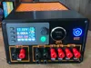
Setup the front panel as shown in the Instructable Page, I soldered all of mine instead of using crimped connectors, using wires that were trimmed from the PSU. Connect multiple wires in parallel if you want to run higher amperages on this, i doubled up one 12V jack to let me run 20 amps if needed. I'm currently using 10Amp fuses in all of the fuse holders.
Sink your threaded inserts into their locations and then assemble!
Enjoy and good luck!!

Comment & Rating (1)