
Logitech G703 Fingertip Mod (34g wired)
Print Profile(1)
Description
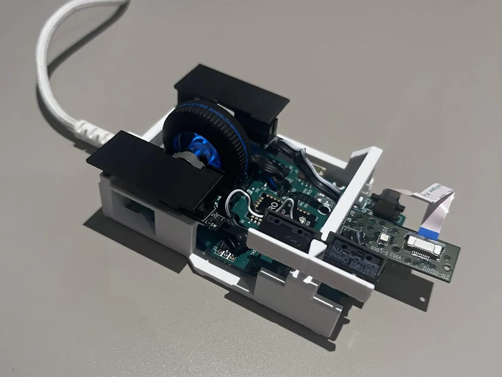
This Logitech G703 fingertip mod is a modification of Vegardbp model. The main modification includes the placement of the side button and overall structural integrity of the model. This model can be printed with both PLA and PETG though PETG is preferred for the side buttons flexibility. I just want to add that this model is customized to my finger placements hence modification of side panels can be made if you find it to be uncomfortable.
G703 component requirement
RMB, LMB, two side switches attached to top PCB (all found on top chassis)
Main PCB
Scroll wheel + button and scroll wheel mount
Battery, DPI button (optional)
2 long M2 screws, 1 short M1 screw, 4 tiny M1 screw
Instruction:
After stripping off the required components from the original G703, you can choose to remove the battery if you want to use this wired only. The DPI button was also removed as DPI can be changed in software. For easier installation, you can separate the top PCB from the main PCB through the flexible connector.
Remove the scroll wheel from rotary encoder then slide the main PCB into the 3d printed chassis, make sure it sits on top of the two screw holes in the front.
Install the bottom scroll wheel mount to the main PCB and chassis using M2 screw (The longest screw you find from taking apart G703, idk which compartment to be exact)
Put the scroll wheel back to the rotary encoder and screw both that and the scroll wheel button onto the scroll wheel mount with 4 tiny M1 screw ( should be the same from when you took it apart)
Install the side switches (the back switch wire might get stuck on the support behind it, make sure to have the wire wrapped under first or else the side button will not sit well in the slot)
Install the two printed flaps in the front slot of the chassis, make sure the RMB and LMB are placed in the hole provided (you can glue them on if you want but they should stay once your flap are on top of it). Make sure that you can feel the button click after installing the two flaps.
Now plug back in the top and main PCB, you can choose to bend some of the wires to make sure button stay in place.
This remix is based on

License



Comment & Rating (0)