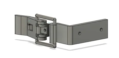
PETG Locking Clip


Print Profile(1)
Bill of Materials


Description
Designed with practical print tolerances, but fitment may vary slightly depending on printer calibration and—most importantly—filament profile settings. Material behavior has a big impact, especially with PETG.
The prototype used for testing was printed with PETG that was slightly on the humid side (which, coincidentally, is exactly why I'm building a filament drying box… so this latch may have started its life solving its creator’s own problem).
Minor sanding or small tolerance adjustments may be needed depending on your setup, but overall dimensions should print very close to spec on a well-tuned machine.
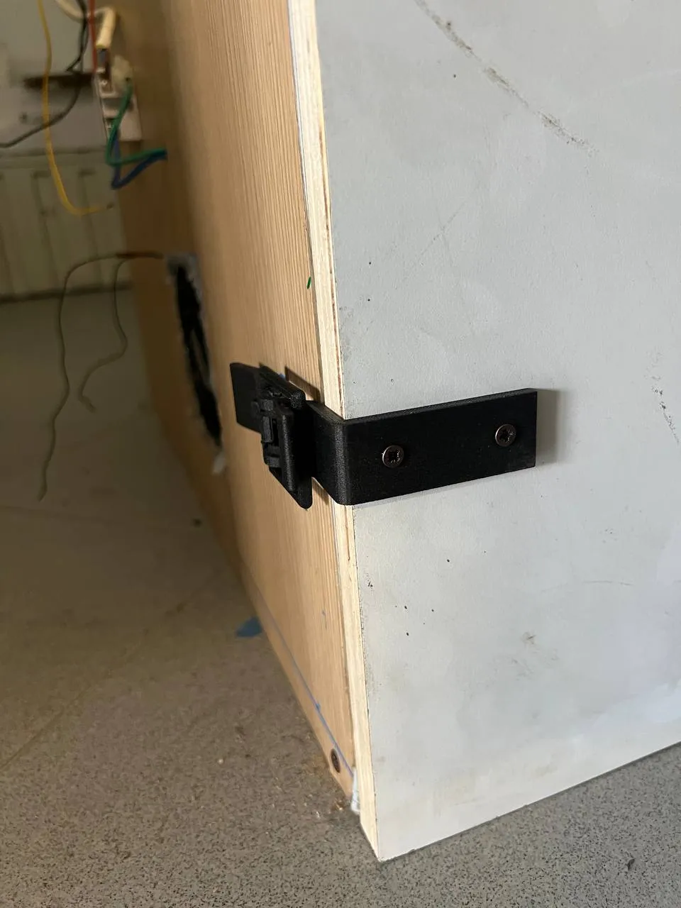
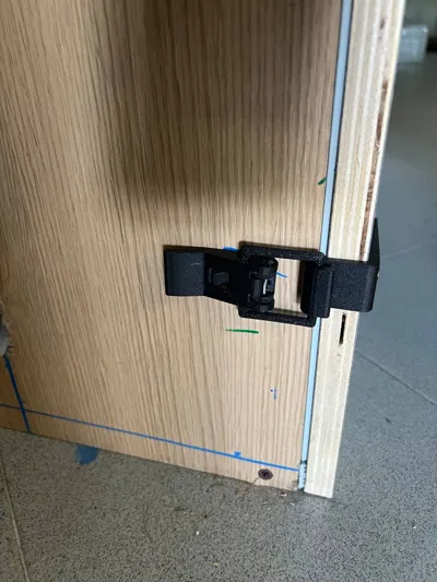
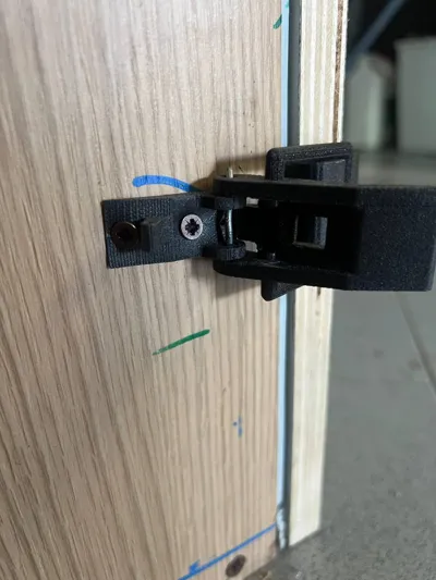
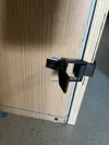
The base plate and catch plate are designed to be mounted using screws.
Use at least 2 screws per part for proper alignment and holding strength, although additional screws can be used depending on your application and enclosure size.
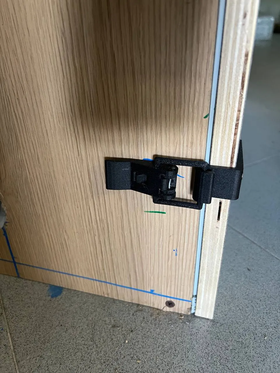
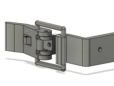
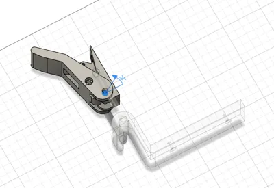
The pivoting latch arm must be assembled using a 2.5 mm steel pin (a standard nail or compatible metal rod can also be used). Insert the pin through the aligned hinge holes to create the pivot point for the locking mechanism.
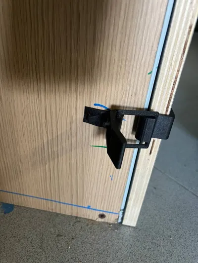
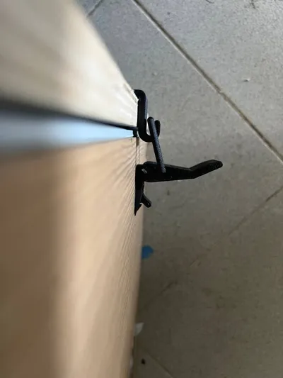
The retaining clip / latch arm is designed to slide into its guide grooves. Gently flex it open slightly during installation, just enough to guide it into the channels without overstressing the printed part. Once seated, it should move freely while remaining securely captured in place.
Final fit and movement may vary slightly depending on filament tuning, print profile, and material moisture content — because sometimes PETG likes to remind us it has personality.
Comment & Rating (1)