
Anycubic Chiron-BTT SKR2 Conversion Parts
Print Profile(1)
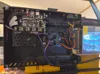
Description
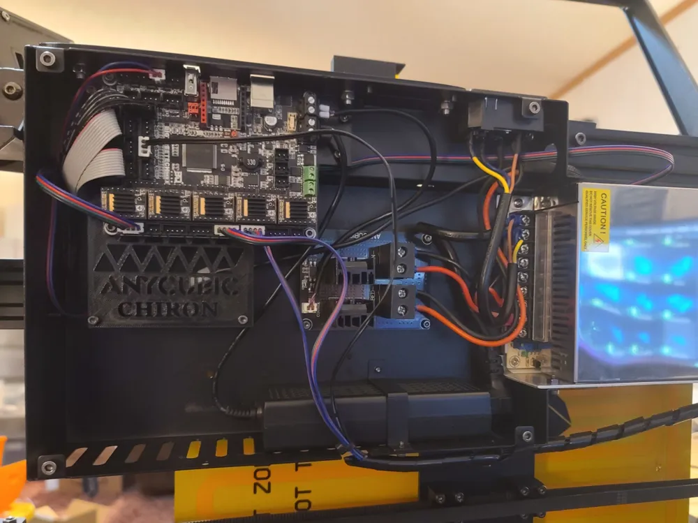
This conversion WILL REQUIRE CUTTING the stock housing to adapt.
This will also require REWIRING/EXTENDING existing wires since it no longer utilizes the stock side plate for the toolhead/gantry wiring.
Board mounts to the adapter plate using 4x M3 heatset inserts and the stock screws from the trigorilla setup.
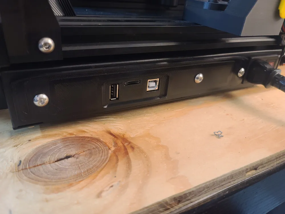
Side panel mounts using 3x M5x10mm buttonhead bolts with lockwashers and nuts.
Parts to swap the stock Trigorilla board and parts for the BigTreeTech SKR2 mainboard in the Anycubic Chiron printer using the stock housing.
Parts should be printed in ABS or at minimum PETG for heat resistance since in direct contact with the PCB.
After printing the parts, remove the trigorilla board and all other sub boards connected to it from the enclosure, (ideally remove all components and remove the enclosure in its entirety for ease of modifying).
Mount the adapter plate up, and mockup the skr2 board to see where the USB/SD ports lineup on the side panel. Mark the area they will collide with (leaving a few mm spare beyond the needed area). Doublecheck before cutting that your marks are correct then cut the small area from the side of the enclosure.
Next mount the plate and board in, then align the holes in the side panel with the board ports (the flat side of the plate should face against the enclosure) to get the mounting location for your screw holes, Mark the center of the 3 round holes in the side panel. Remove the board and mounting plate one last time, and then drill out the screw hole locations with an appropriately sized drill bit. i cant recall what size i used specifically, but it should fit an M5 bolt without binding.
I cleaned up all areas where cutting and drilling was done with a file, then masked off the enclosure with painters tape and repainted the area around the cutout sections where i removed metal at this point, but it should be hidden and shouldnt interfere with anything physically if you choose not to.
Then finally reinstall the mounting plate, install the side panel, and then the board and finish up the wiring.
License

You shall not share, sub-license, sell, rent, host, transfer, or distribute in any way the digital or 3D printed versions of this object, nor any other derivative work of this object in its digital or physical format (including - but not limited to - remixes of this object, and hosting on other digital platforms). The objects may not be used without permission in any way whatsoever in which you charge money, or collect fees.


Comment & Rating (0)