Hypoid Gear - Educational Model


Print Profile(1)

Description
My Educational Mechanical Examples Series
This model is one of my educational mechanical mechanism examples on 80mm x 80mm base plates.
You can find all models of the series in this collection => [Mechanical Mechanism Examples]

The present model
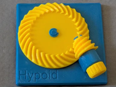
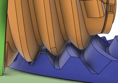
This is an educational model of hypoid gear.


Brief Description
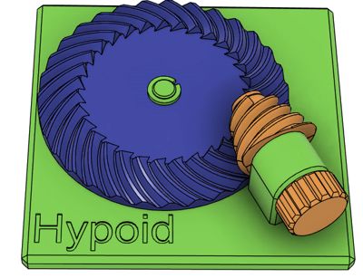
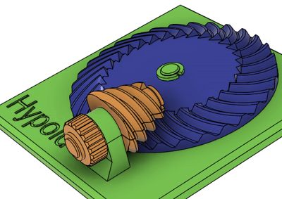
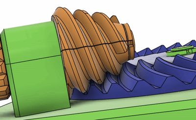
Hypoid gears resemble spiral bevel gears at first glance, but differ fundamentally in that the two rotation axes do not intersect — they are skew (non-intersecting, non-parallel). This configuration allows the overall gear mechanism to be more compact in height. Furthermore, as demonstrated by this model, a large reduction ratio can be achieved by increasing the spiral angle of the pinion and wrapping its teeth around multiple turns in the manner of a worm gear. In this model, the ring gear has 31 teeth and the pinion has 3 teeth, yielding a gear ratio of approximately 10.3:1. Because many teeth are simultaneously in mesh, the load is distributed across multiple contact points, enabling the transmission of large torques. A drawback, however, is that the large sliding motion between tooth surfaces leads to increased friction losses.
The most representative application of hypoid gears is in automobiles, where torque is transmitted from the propeller shaft to the differential gear assembly. The use of a hypoid gear allows the drive shaft to be positioned lower, enabling a reduced floor height in the passenger cabin and avoiding interference with the propeller shaft. For these reasons, hypoid gears are adopted in a wide range of vehicle models.
Despite their prevalence, the design and machining of hypoid gears demand a high level of technical expertise, and the number of manufacturers capable of supplying practical gear-cutting equipment is extremely limited worldwide. Even today, the theoretical design of hypoid tooth profiles remains an active area of research, with findings continuing to be published in peer-reviewed academic journals.
The present model was designed based on the method introduced by D. Dooner et al. in their 2020 paper (with a correction to a possible error in Eq. 28). The design procedure is as follows.
- Define the axis configuration. The skew angle and the center distance between the two rotation axes are specified.
- Determine the pitch surfaces. The pitch surfaces of a hypoid gear pair are two hyperboloids of revolution that are tangent to each other. The common tangent line of both pitch surfaces intersects the common perpendicular of the two axes; by fixing the location of this intersection point (the pitch point), the two pitch surfaces are uniquely determined.
- Determine the spiral angles from the gear ratio. Once the desired gear ratio is specified, the spiral angle of the tooth trace on the pitch surface is determined as a function of position along the common generator line for each of the two gears, from the principle that the relative velocity vector of two rigid bodies must be parallel to the tooth trace when they are rotated around their own axes with the specified gear ratio.
- Compute the tooth profile numerically. The actual tooth profile is obtained by numerically simulating a virtual cutting process of the gear blank with a two-dimensional (2D) rack tool, referenced to the tooth trace curve on the pitch surface. As in the case of involute gears, the tooth flanks of this rack are planar, and its 2D representation is a straight line. The cutting is purely virtual: the tooth flank surface of the hypoid gear is constructed from the locus of points that would be cut most deeply by the tool line, as determined directly from the position and orientation of the tool rather than through step-by-step cutting simulation.
- Vary the pressure angle continuously to avoid interference. Cutting with a constant pressure angle across the full face width would cause tooth interference. To prevent this, the pressure angle is varied continuously as a function of distance from the central axis, so that the two tooth flanks maintain line contact across the full face width.
- (Not implemented in this model.) The paper further discusses detailed tooth profile modifications, which have not been implemented in the present model.
The tooth profiles designed by this procedure have the property that the pressure angle is well-defined at every point on the tooth surface. Notably, although the two tooth profiles are designed independently — rather than one being derived as the conjugate of the other — they nonetheless mesh correctly with each other. This is a remarkable characteristic of the design methodology.
NOTE: It may be noted that a related concept called the hyperboloid gear — which shares the same pitch surface geometry with hypoid gears, i.e. two tangenting hyperboloids of revolution, but uses straight tooth traces along the ruling lines of the hyperboloid — is sometimes introduced in online resources. As far as I understood, however, straight ruling-line teeth cannot achieve proper conjugate action; they require large play between the teeth to avoid interference, and full-width contact is achieved only at the instant when the contact occurs on the pitch surface — away from this position, line contact across the face width will not be maintained. In my opinion, such a gear remains largely a geometric curiosity rather than a practical mechanism. At least, I can assert that theoretically correct tooth shapes of such gears can not be realized just by twisting thick spur gears as described in some resources. Remember even bevel gears have their special tooth shapes (spherical involute) that differ from the planer involute gear.
Reference
Related Models
- Hypoid gear resembles to spiral bevel gears, which is included in “Educational Gear Examples 2”, except that the pinion axis is shifted from the center.
- Hypoid gear has a skew configuration of two axes.
- Worm gears, which are included in “Educational Gear Examples 1” and “Educational Gear Examples 2”, and Globoidal Worm Gear system also have skew configurations of axes.
- Screw gear which is included in “Educational Gear Examples 1” also has a skew configurations of axes.


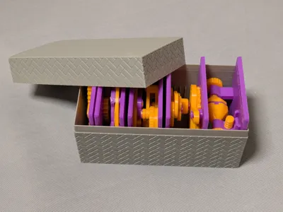
Case
This model is compatible with the case included in my first set.

Printing
- Use the models named ???-printable.stl for printing.
The models named ???-assembled.stl are provided just to show how they should be assembled.
- Use well-dried PETG to have better dimensional accuracy.
- Use 0.1 mm or 0.08 mm layer height to have smoother surfaces.
- Use slow printing speed for overhangs.
- Select “Random” seam position to have smoother rotation.
Randomly distributed seam should be easily worn out after some wearing.Printing
Sanding and Filing
Note that, in this model, the rotation of the bases for bearings is intentionally made not too smooth.
Sometimes, the gears suffer from the stringing effect and/or elephant foot effect, resulting in a too tight fit to the shafts (they are designed with a 0.15 mm radial clearance).
If you see rough surface on the shafts due to stringing, sand off the roughness with a small piece of sand paper.


If you feel the gears do not rotate smoothly due to an elephant effect, widen the hole slightly by using a thin round bar file.

Without those issues, the parts should rotate very smoothly with minimal friction.
Assembly
First, secure the larger gear onto the central shaft with a retaining ring.
The small gear is split into two halves for better precision in printing.
Combine the two with aligning them by the cylindrical key and secure them with the shaft through the bearing.
Finally, secure the gear and shaft with the other retaining ring.

Other examples
You may also be interested in the models in my educational mechanical mechanism examples.
Find them in this collection:
https://makerworld.com/collections/15048577-my-educational-mechanism-models
Happy printing!
Acknowledgement
I got into gears thanks to K.$uzuki's amazing articles and YouTube videos. Many of the mechanisms shown in this series came from the introductions on his website. He also makes excellent gear models himself. This series wouldn’t have existed without his inspiration.
I learned a lot about technical detail of designing gear tooth profiles from Haguruma-No-Hanashi website. I’m truly grateful for that.
License
- The 3D model(s) are licensed under Creative Commons Attribution 4.0 International.
- However, the text and images on this page are copyright reserved.
Comment & Rating (1)