Search models, users, collections, and posts

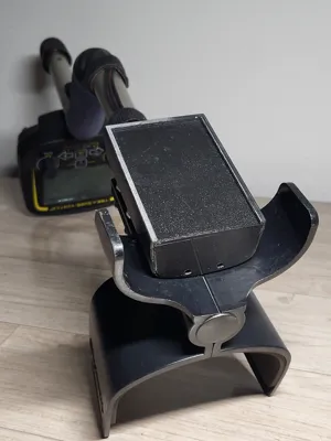
Universal 3S Li‑ion Power Pack for Metal Detectors
IP Report
Print Profile(1)
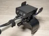
0.2mm layer, 3 walls, 15% infill
Designer
4.9 h
1 plate
Open in Bambu Studio
Boost
2
4
0
0
2
0
Released
Description
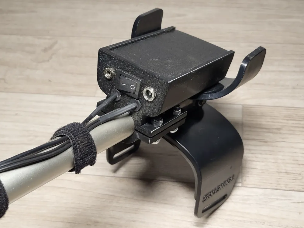
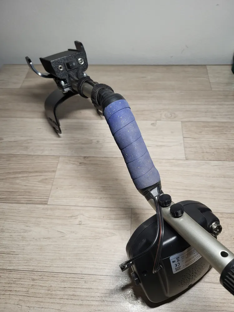
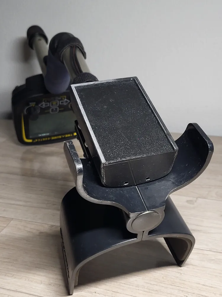
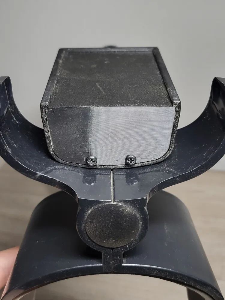
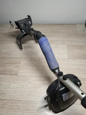
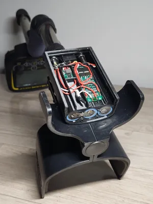
A simple and compact 3S Li‑ion power module designed for metal detectors that use a Teknetics‑style armrest mount. With an adjustable step‑down converter, it can also power any device that normally runs from 9 V, or any voltage within the converter’s range.
The design is modular, serviceable and easy to print. Ideal for users who want to replace a classic 9V battery with a modern 3S Li‑ion solution.
Compatibility
Mechanical
Fits detectors with the Teknetics‑style armrest mount, including:
- Teknetics G2 / G2+
- Fisher Gold Bug Pro
- Teknetics Alpha / Delta / Gamma
- All G2‑like clones
- Any detector using the same armrest geometry
Electrical
- Adjustable output (typically set to 9 V)
- Suitable for any device within the step‑down module’s voltage range
- Can be used as a general‑purpose 3S Li‑ion power pack
Print Settings (PETG)
- Layer height: 0.2 mm
- Infill: 15%
- Perimeters: 3
- Supports: yes (only under the internal module‑separating slots)
- Brim: no
- Orientation: all parts printed vertically
All parts fit on a single build plate
Bill of Materials (BOM)
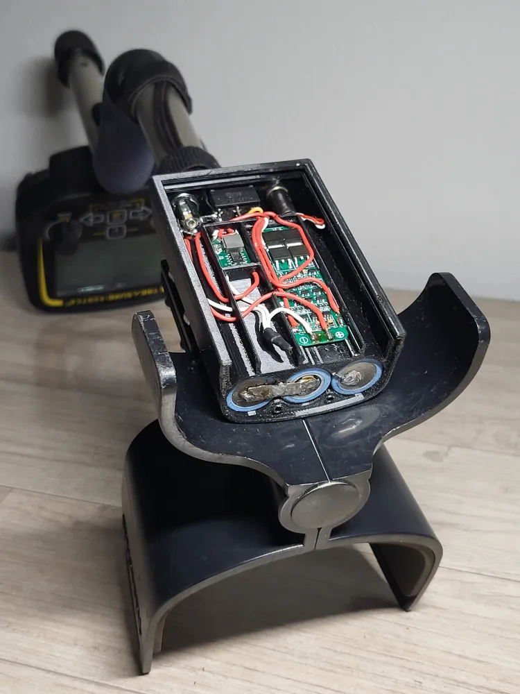
- 3× 18650 Li‑ion cells (flat‑top)
- 3S BMS, 20 A (58×20 mm)
- MP2307 step‑down module (12×18 mm)
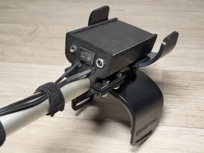
- Rocker ON/OFF switch (panel cutout 19×12.5 mm)
- 3.5 mm stereo panel‑mount jack – standard type, can be replaced with another connector if needed
- Panel‑mount charging connector (7.8 mm hole) – universal hole size, works with multiple DC connector types
- 470 µF/16V electrolytic capacitor – common value, other similar values also work
- Power twin‑lead cable + shielded stereo cable – length and gauge depend on the detector setup
- 2× rubber grommet (5 mm hole) – the hole is a base size; can be enlarged with a drill to fit any grommet
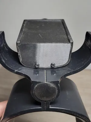
- 2× screws for the cover (M3 or small self‑tappers) – anything that fits the printed holes is fine
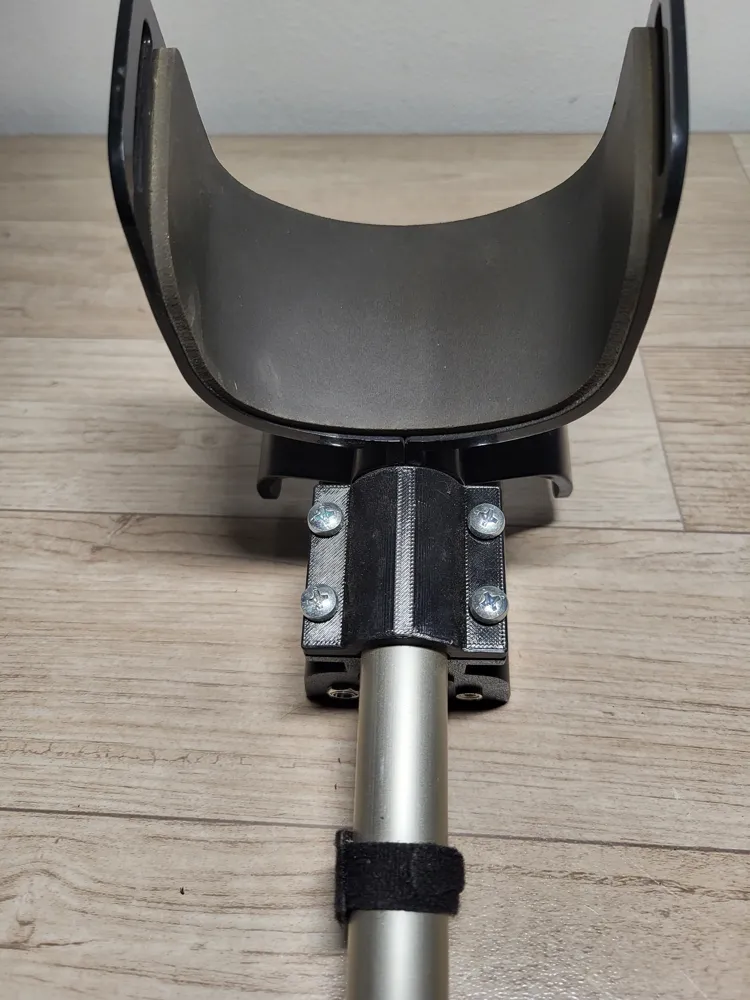
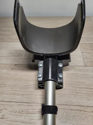
- 4× M5×15–20 mm screws and nuts for clamp
- Nickel strip for battery pack (thickness not critical)
- Rubber grommet (any size that fits the hole)
Assembly
- Print all parts – all components are designed for vertical printing and fit on a single plate
- Build the 3S battery pack – spot‑weld or solder the 3× 18650 cells into a 3S configuration. Connect the cells using thin nickel strip. Solder the balance wires (B1, B2) and main leads (B+ / B–) – route the balance wires through the battery slots before connecting the BMS
- Connect the BMS – connect B+, B–, B1, B2 to the pack – the BMS output (P+ / P–) is used for both charging and powering the detector
- Wire the charging connector – connect the BMS output directly to the panel charging connector – ensures the pack is always charged through the BMS protection
- Install the rocker switch and step‑down module – from the charging connector, route the positive lead through the rocker switch – from the switch output, connect to the step‑down input – the negative lead goes directly from the BMS output to the step‑down input
- Install the audio jack – the 3.5 mm jack is simply bridged (straight‑through connection) – it does not interact with the power circuit
- Solder the output power cables - solder two 0.5 mm² power wires (positive and negative) that will go to the detector. Route them through the grommet toward the enclosure exit. These wires will later connect to the detector’s power input
- Solder the shielded stereo cable for the audio jack - use a shielded stereo cable. Left and right channels are bridged (joined together). Connect the bridged signal to the jack’s tip/ring. Route the cable through the grommet toward the detector.
- Add the 470 µF/16V capacitor – solder the capacitor to the step‑down output – alternatively, place it directly on the output cable going to the detector
- Close the cover and secure it with screws
- Attach the module to the detector armrest – use 4× M5 screws, 15-20 mm length and 4x M5 nuts
Notes
- The design is not waterproof — intentionally, to keep it simple and serviceable.
- The slots are sized for the listed modules.
- Connector holes are universal and can be adapted if needed.
License

This user content is licensed under a
Creative Commons Attribution-Noncommercial-Share Alike


Comment & Rating (0)