Ellipse Compass - Educational Model


Print Profile(1)

Description
My Educational Mechanical Examples Series
This model is one of my educational mechanical mechanism examples on 80mm x 80mm base plates.
You can find all models of the series in this collection => [Mechanical Mechanism Examples]

The present model
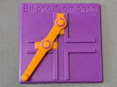
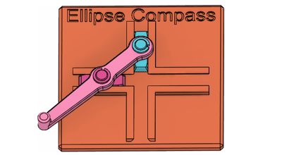
This is an educational model of an Ellipsograph, i.e. ellipse compass, also known as the trammel of Archimedes.


Brief Description
This mechanism is known as the trammel of Archimedes. There, two shuttles (trammels) slide along a pair of orthogonally intersecting linear guides. A rod is coupled to these shuttles via rotational pivots, and as the assembly moves, the free end of the rod traces a perfect ellipse.
The geometry becomes transparent with a little trigonometry. Let a denote the distance between the two pivots, b the distance from the inner pivot to the tip of the rod, and θ the instantaneous angle of the rod. The inner pivot is constrained to move horizontally, so its position is (a cos θ, 0), while the tip traces the path
(x, y) = ( (a+b)cosθ, b sinθ ).
Eliminating θ yields the standard equation of an ellipse:
x² / (a+b)² + y² / b² = 1
with semi-major axis (a + b) along the x-axis and semi-minor axis b along the y-axis. Varying the pivot spacing a therefore changes the eccentricity of the ellipse without altering the minor axis — a remarkably elegant property of this simple linkage.
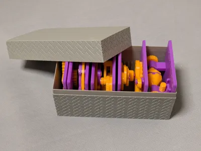
Case
This model is compatible with the case included in my first set.

Printing
- Use the models named ???-printable.stl for printing.
The models named ???-assembled.stl are provided just to show how they should be assembled.
- Use well-dried PETG to have better dimensional accuracy.
- Use 0.1 mm or 0.08 mm layer height to have smoother surfaces.
- Use slow printing speed for overhangs.
- Select “Random” seam position to have smoother rotation.
Randomly distributed seam should be easily worn out after some wearing.Printing
Sanding and Filing
Note that, in this model, the rotation of the bases for bearings is intentionally made not too smooth.
Sometimes, the gears suffer from the stringing effect and/or elephant foot effect, resulting in a too tight fit to the shafts (they are designed with a 0.15 mm radial clearance).
If you see rough surface on the shafts due to stringing, sand off the roughness with a small piece of sand paper.

If you feel the gears do not rotate smoothly due to an elephant effect, widen the hole slightly by using a thin round bar file.

Without those issues, the parts should rotate very smoothly with minimal friction.
Assembly
Insert the trammels into the guide rails.
Then, secure the rod onto the shafts on the trammels by the retaining rings.
Other examples
You may also be interested in the models in my educational mechanical mechanism examples.
Find them in this collection:
https://makerworld.com/collections/15048577-my-educational-mechanism-models
Happy printing!
Acknowledgement
I got into gears thanks to K.$uzuki's amazing articles and YouTube videos. Many of the mechanisms shown in this series came from the introductions on his website. He also makes excellent gear models himself. This series wouldn’t have existed without his inspiration.
I learned a lot about technical detail of designing gear tooth profiles from Haguruma-No-Hanashi website. I’m truly grateful for that.
License
- The 3D model(s) are licensed under Creative Commons Attribution 4.0 International.
- However, the text and images on this page are copyright reserved.
Comment & Rating (2)