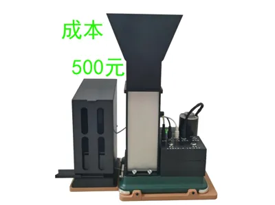
6.5MM Automatic Cigarette Rolling Machine Part 3: Feeder


Print Profile(1)
Description
Boost Me (for free)
If it's useful, remember to like, share, and subscribe! Thanks~!
This is the feeder part of the 6.5MM automatic cigarette rolling machine, adapted for the 6.5mm Hermit Crab second-generation Roman foot model. If you want the full set, check my homepage. Let's get started without further ado.
Hardware:
M2*10 socket head cap screws 2 pcs,
M2.5*8 flat head screws 4 pcs,
M3*5 flat head screws 4 pcs,
M3*12 socket head cap screws 4 pcs,
M4*25 socket head cap screw 1 pc,
M3 spring washers 4 pcs,
M3*8 flat washers 6 pcs,
M3 high knurled nuts GB806 2 pcs.
Diameter 10*2.5 strong magnets 19 pcs,
Diameter 6*1.3 strong magnets 16 pcs,
PTFE tube outer diameter 4 inner diameter 2mm length 3mm 2 pcs,
DC5.5*2.1 plug with 200mm long cable 1 pc,
DC3.1*1.3 plug with 200mm long cable 1 pc,
DC motor speed controller 4.5V-30V 5A 1 pc,
Dual MOS delay switch circuit module 5-36V 15A 1 pc,
24V cigarette rolling machine vibrating feeder motor 1 pc, (Alternatively, a 555 mini vacuum pump motor can be modified. Note that the voltage must be 24V. Remove the front cover, prepare an M4 threaded rod about 50mm long, two M4 nuts, and a rod end bearing SI4P/K. Screw one end into the pump and lock with an M4 nut, screw the other end into the rod end bearing and lock with an M4 nut.)
Several wires.
Dual MOS delay switch circuit module 5-36V 15A,

DC motor speed controller 4.5V-30V 5A,


First, be careful when removing supports. Don't use too much force. Remove them slowly with pliers. After removal, make sure all support points at the bottom are clean, especially the slots for the magnets. Use a flathead screwdriver to rub them repeatedly a few times to ensure the bottom is flat and not bulging after installing the magnets.


Wiring diagram.

Install the LED and fix it with solder.

Remove the LED after completion.

Insert it from the bottom all the way to the end of the slide.

Screw in 2 M2.5*8 flat head screws on each side and tighten them.

Insert the soldered LED.

Solder the wires to the vibration motor, install it as shown, and screw in M3*12 socket head cap screws with spring washers and flat washers. Tighten them but not with excessive force.

Install the DC cables, insert them into the two holes at the back as shown.

Connect the wires according to the wiring diagram. Be careful not to mix up the positive and negative terminals. The wiring should look like this after connection.

Fix the delay circuit board with M3*5 flat head screws as shown.

Insert the speed controller in the direction shown.

Arrange the wires.

Install PTFE tubes on both sides. The PTFE tubes will serve as bearings.

Place the vibrating plate like this.

Install M2*10 socket head cap screws with M3 flat washers. Do not overtighten.

Screw in an M4*25 socket head cap screw from the left side.

Push the vibrating plate all the way forward until there is about 10mm clearance at the front as shown. If not, remove the vibrating plate, adjust the screwing depth of the rod end bearing, then lock it.

Insert the other transparent plate into the slide until it reaches the bottom. This plate can also be replaced with a 4mm thick acrylic plate.

Install diameter 10*2.5 strong magnets in the same direction at the bottom. Note that magnets should not be installed in the position where the screwdriver is pointing as shown.


Install diameter 6*1.3 strong magnets at the top and upper bottom. Be careful not to install the magnets in the wrong direction.

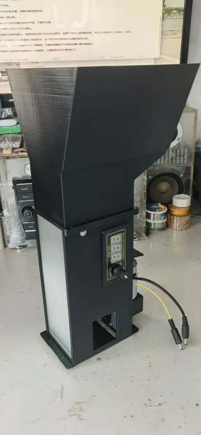
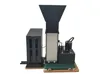
Finished effect.

The M3 high knurled nuts are used to fix it to the machine.

License
You shall not share, sub-license, sell, rent, host, transfer, or distribute in any way the digital or 3D printed versions of this object, nor any other derivative work of this object in its digital or physical format (including - but not limited to - remixes of this object, and hosting on other digital platforms). The objects may not be used without permission in any way whatsoever in which you charge money, or collect fees.
Comment & Rating (0)