Sim HandBrake DIY


Print Profile(1)

Description
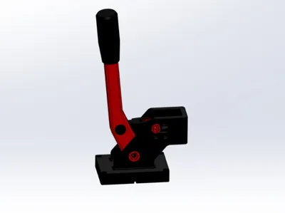
🏁 DIY Sim Racing Handbrake (ESP32-S3 USB)
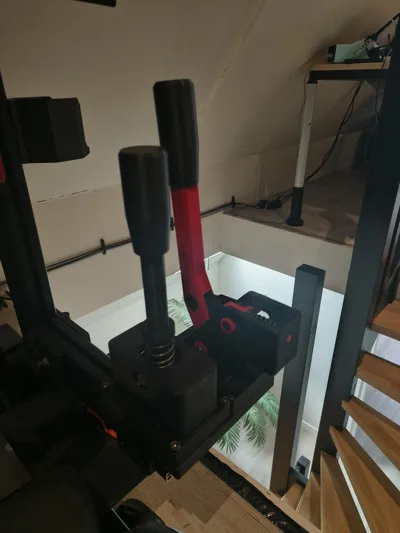
+ Optional Sequential Shifter Support (included in firmware below!)
If there is enough interest, I will also release a full DIY Sequential Shifter design in the future.
The firmware already supports both the handbrake and the shifter.
🔥 Introduction
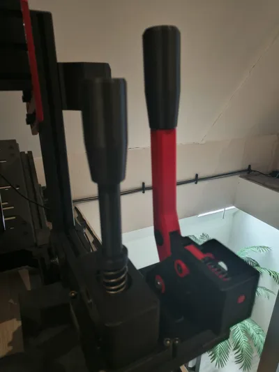
This is a DIY analog sim racing handbrake designed for PC racing games like rally simulators and track racing titles.
It uses an ESP32-S3 with native USB to act as a plug-and-play HID device — no external Arduino or USB converter needed.
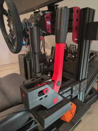
The design is compact, strong, and fully 3D printable, using mostly standard hardware components.
The handbrake works analog, meaning the position directly affects braking force — just like a real hydraulic handbrake.
🎮 Features
- ✅ Analog handbrake (linear position → braking force)
- ✅ USB HID via ESP32-S3 (plug & play on PC)
- ✅ Optional sequential shifter support (via firmware)
- ✅ Fully 3D printable
- ✅ Uses common, easy-to-source hardware
- ✅ Spring-loaded return (compression spring)
🧾 Bill of Materials (BOM)
Electronics
- ESP32-S3 (Super Mini recommended)
- 10K Linear Slide Potentiometer
👉 https://nl.aliexpress.com/item/1005003684684538.html - 3-wire cable (for potentiometer connection)
Hardware
- M8 nut
- M8x50 socket head bolt
- M8x16 bolt (1x)
- M6x12 bolt (1x)
- M3x8 or M3x10 bolts (4x)
- Threaded rod M10 (60–70mm)
- Compression spring
- Length: 40–50mm
- Wire thickness: ~2.5mm
- Outer diameter: max 19mm
Printed Parts
Included in this project:
- Base (Body)
- Lever / Hand lever
- Shaft components
- Lock shaft
- Rings / spacers
- Spring holder
- Lever shaft system
- Horizontal guiding shaft + ring
- Potentiometer bracket (linear mount)
- Top shaft + bolt parts
- Handle
(All parts are included in the STL files)
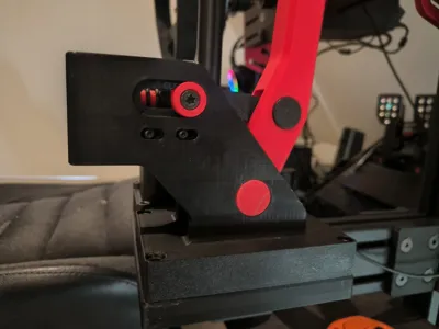
🧱 3D Printing Notes
For the best surface quality, I used PLA/PETG support interface filament.
This gives a much cleaner finish on supported surfaces compared to standard supports.
Recommended materials:
- PLA → easy to print, good enough for most use cases
- PETG → slightly stronger and more durable
Stronger materials are always possible if you want extra rigidity or long-term durability.
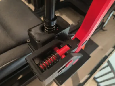
⚙️ How it Works
The handbrake uses a linear sliding mechanism:
- The lever pushes a slider
- The slider compresses a spring
- At the same time, it moves the linear potentiometer
- This gives a smooth analog signal to the ESP32
Important:
- This uses a compression spring, not a tension spring
- The return force comes from pushing the spring back
🔌 Wiring (ESP32-S3)
The potentiometer has 3 pins:
- Middle pin → GPIO (analog input)
- Side pin → 3.3V
- Other side → GND
⚠️ Use 3.3V only, not 5V
The firmware reads this signal and converts it into a USB axis.
💻 Firmware
- Firmware is included with this project
- Supports:
- Analog handbrake (X-axis)
- Sequential shifter (2 buttons)
You can use:
- Only handbrake ✔
- Handbrake + shifter ✔
🎮 Setup in Windows
- Connect the ESP32 via USB
Open:
joy.cpl
- Select the device
- Click Properties
- Move the lever → should respond on an axis
Optional:
- Use Calibrate to fine-tune the range
🏎️ In-Game Setup
In games like:
- Assetto Corsa
- Dirt Rally
- iRacing
Simply:
- Assign handbrake → pull lever
- Assign shift up/down → press buttons
⚠️ Notes
- This is a DIY project, some basic technical skills are required
- ESP32 works as a PC USB device only (no direct console support)
- If something is missing or truly incorrect, feel free to report it
- Small improvements or “nice-to-have” suggestions are not needed
🚀 Future Plans
If there is enough interest, I will release:
👉 A full DIY Sequential Shifter (mechanical design) to match this handbrake
❤️ Final words
This project is designed to give you a realistic sim racing experience with minimal cost and maximum customization.
Build it, tweak it, improve it — and enjoy rallying the way it should be. 🏁
🔧 Firmware (Arduino / ESP32-S3)
#include "USB.h"
#include "USBHID.h"
USBHID HID;
const int handbrakePin = 2;
const int upShiftPin = 6;
const int downShiftPin = 7;
// HID report buffer: 1 byte knoppen, 1 byte X, 1 byte Y
uint8_t report[3];
void setup() {
Serial.begin(115200);
pinMode(handbrakePin, INPUT);
pinMode(upShiftPin, INPUT_PULLUP);
pinMode(downShiftPin, INPUT_PULLUP);
HID.begin();
USB.begin();
Serial.println("ESP32-S3 USB HID Gamepad gestart!");
}
void loop() {
// Handrem uitlezen
int rawHandbrake = analogRead(handbrakePin); // 0–4095
int8_t mappedHandbrake = map(rawHandbrake, 0, 4095, -127, 127);
// Knoppen uitlezen
bool upShift = (digitalRead(upShiftPin) == LOW);
bool downShift = (digitalRead(downShiftPin) == LOW);
report[0] = 0;
if (upShift) report[0] |= 1;
if (downShift) report[0] |= 2;
report[1] = mappedHandbrake;
report[2] = 0;
// HID report sturen (report ID = 1)
HID.SendReport(1, report, sizeof(report));
delay(10);
}
License
You may create derivative works based on this object, provided that all such derivative works are published exclusively on the MakerWorld platform and include proper attribution to the original creator. You may not share, upload, host, distribute, or publish this object—or any derivative work of this object—on any other digital platform, marketplace, or distribution channel. Commercial use of this object and any derivative works is strictly prohibited. This includes, but is not limited to, selling, renting, sublicensing, or using the object in any context in which you receive monetary compensation or other financial benefits.
Comment & Rating (15)