Support Test


Print Profile(6)
Description
Advanced Support Calibration
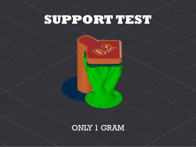
The goal of these models is to provide a comprehensive test bench to find the perfect "sweet spot": supports that ensure a smooth and precise bottom surface, yet detach easily without fusing with the main print.
Included Geometries
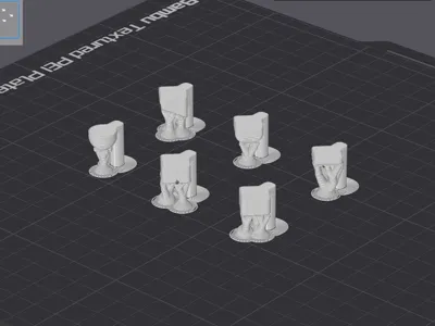
The set includes various geometric scenarios, each designed to stress the 3D Printer:
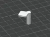
- Flat Base: Tests the support's ability to create a uniform horizontal plane
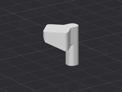
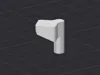
- Inclined Base: Evaluates "stair-stepping" management. Checks lateral stability and how Z distance performs on diagonal planes
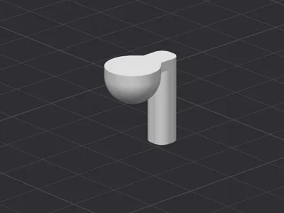
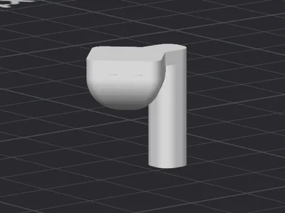
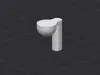
- Spherical Surface: Tests the support's ability to follow gentle curves that progressively become extreme overhangs, checking detachment on rounded geometries
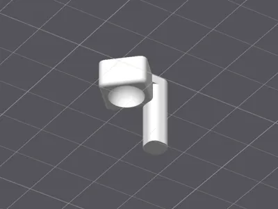
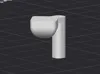
- Concave Surface: Challenges internal supports and the risk of lateral (XY) fusion on the model's inner walls
Fundamental Parameters
To get the most out of this test, you need to focus on the two parameters that influence 80% of the final result.
1. Top Z Distance
This is the most critical and, often, the most misunderstood parameter. The Z Distance must ALWAYS be an exact multiple of the layer height you are using.
- The mechanical limit: The 3D Printer moves along the Z-axis in discrete "steps" (e.g. every 0.2 mm). The machine is not capable of taking "half a step" (e.g. 0.1 mm) to print the end of the support and another half step to start the part
- The common error: If you print with a 0.2 mm layer and set a Z Distance of 0.3 mm, the slicer will be forced to round (often to 0.2 mm or 0.4 mm). This creates discrepancies between what you see on screen and the physical result, leading either to supports fused with the part, or supports too far away causing the overhang to collapse
- The golden rule: Use 1x layer height (e.g. 0.2 mm distance for 0.2 mm layers) for standard detachment, or 2x layer height (e.g. 0.4 mm) if you use sticky materials like PETG and are willing to sacrifice some surface quality for very easy detachment


2. Top Interface Spacing
The interface is the "roof" of the support on which your model rests.
- Wide spacing (e.g. 0.5 mm): The support will be very easy to remove, but your model's filament will sag into the gaps, leaving a rough and "spaghetti" bottom surface
Dense spacing (e.g. 0.1 mm or 0 mm): Creates an almost solid surface. The model will rest on a perfect plane, ensuring excellent aesthetic quality. However, if your Z Distance is not calibrated correctly, such a dense interface will permanently fuse to the part

License
You shall not share, sub-license, sell, rent, host, transfer, or distribute in any way the digital or 3D printed versions of this object, nor any other derivative work of this object in its digital or physical format (including - but not limited to - remixes of this object, and hosting on other digital platforms). The objects may not be used without permission in any way whatsoever in which you charge money, or collect fees.
Comment & Rating (6)