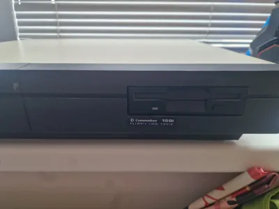
Commodore 128D internal 1581 disk drive


Print Profile(1)
Description
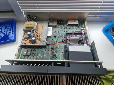
Attempting to improve on the perfection that was the 128D, Commodore engineers got their hands on a Commodore 128 motherboard and attempted to create another "D" (for desktop) variation based around their up and coming 1581 3.5" disk drive, instead of the normal 1571 5.25" version already designed. Sadly this version has never passed into production and stayed as a one of a kind prototype. Until now, I have custom designed and 3d printed a series of parts that allows us to mount a reproduction 1581 disk drive in place of the 1571, essentially recreating of a prototype.
In the context of the Commodore 128Dcr:
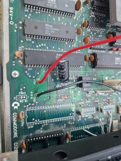
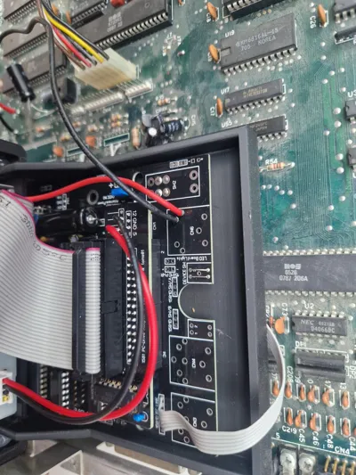
- in order to connect a 1581 in the place of the 1571 the first thing you need to do is disconnecting the 1571 from the IEC bus. To do that you need to remove the IC U113 from the board, because pin 1 of the U113 is the ATN signal. You can desolder the chip or just cut the legs.
- in the C128Dcr thre is 2 test points towards the front middle of the board for 5v and gnd, you can solder wires to this places for powering up the board.
- while building a 1581 board for this project do these: do not solder any DIN 6 connectors onto the board instead connect 6 wires to the “IEC link” behind those connectors, do not put DIN4 power connector but connect 2 wires directly to the where the 5v will be fed into the board(1581 replicas do not need 12V), set the device ID to 8 using permanent connections, configure the board to use the original power plug as power source.
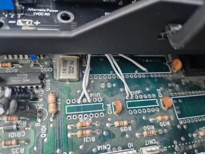
- you can get the reset signal for the 1581 from the 1571's CPU's reset line itself.
- remaining 4 IEC bus signals can be found on U112 or U114.
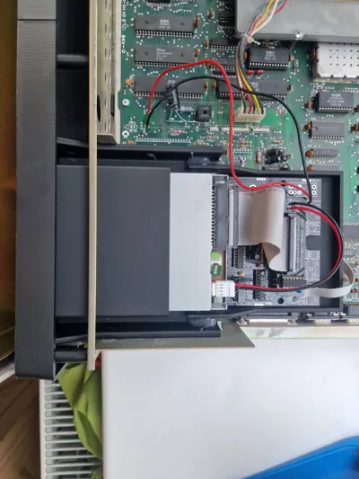
After you finished the 1581, solder wires to the 1581 board first. Cables should be at least 15cm in lenght. First thing you need to do is mount the floppy drive to the floppy holder and 1581 board to the board holder. After that make the connections between C128D and 1581. Then insert the floppy drive from the front, while pushing it back lift the 1581 board holder so it will slide onto the floppy board holder. Finally secure the floppy drive using M3 screws(you need to put threaded inserts first) glue the board holder to floppy holder and connect the floppy drive.
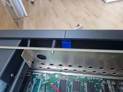
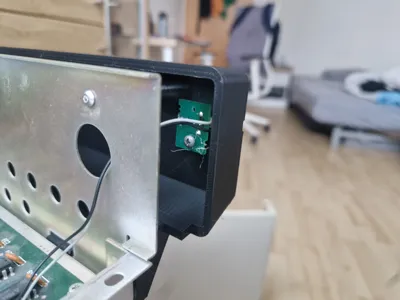
you need M3 screws and some threaded inserts. threaded inserts are for 3 standoffs for the front panel and 3 for the floppy drive holder.
Comment & Rating (0)