Phone Holder For car CD-slot System


Print Profile(1)
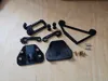
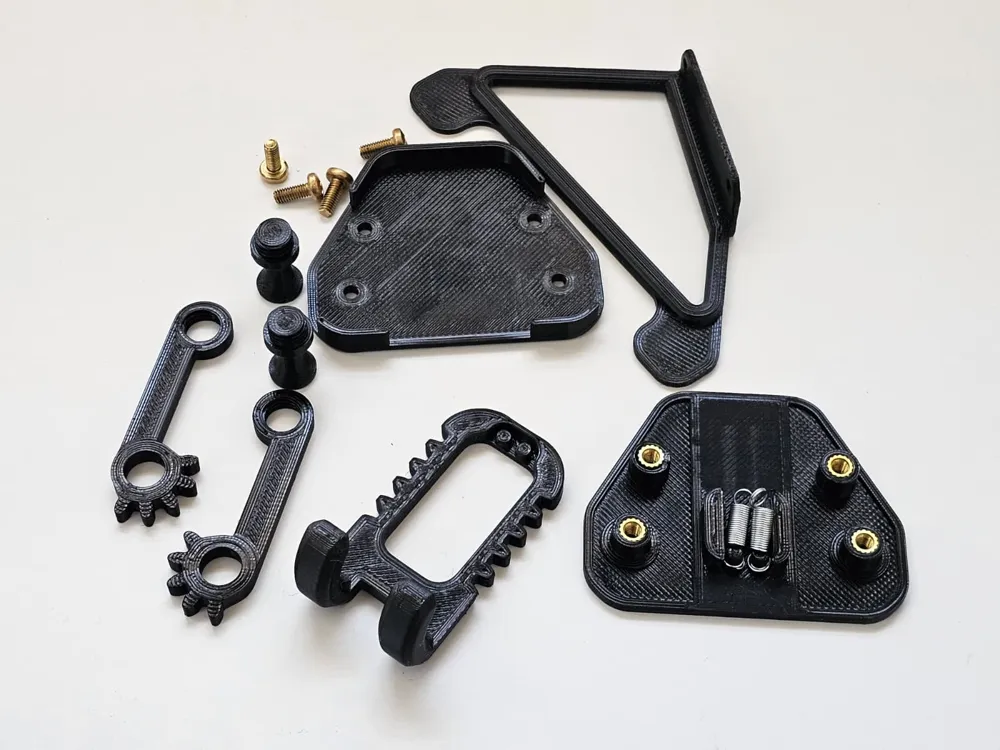
Bill of Materials

Description
Looking for the version with 3d-printed M6 screws? Click here! https://makerworld.com/en/models/2737300-phone-holder-for-car-cd-slot-no-metal-screws?from=search#profileId-3034879
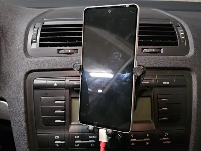
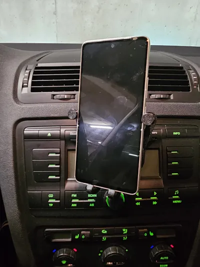
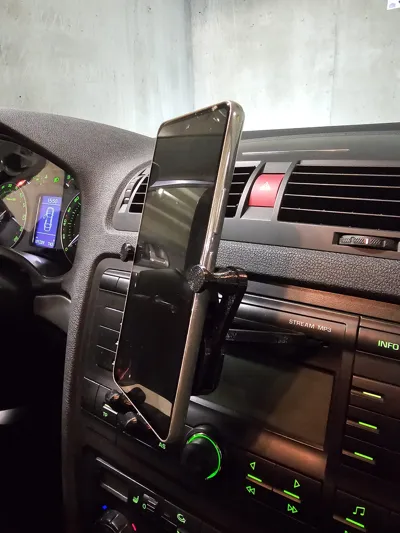
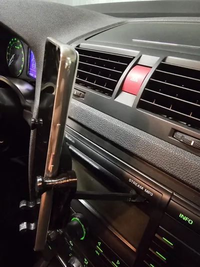
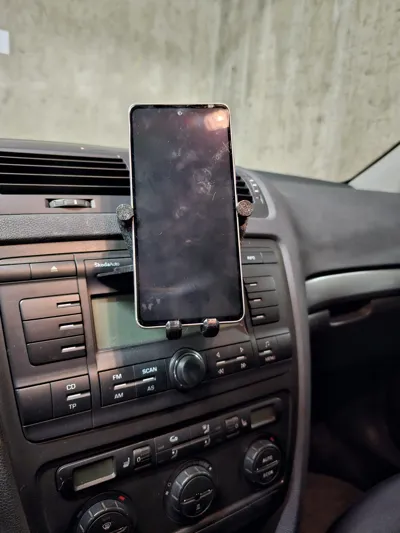
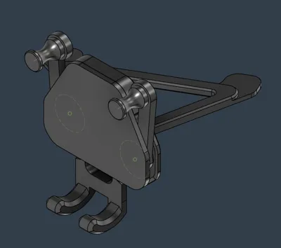
A robust, mechanical phone holder designed specifically for the Skoda Octavia MK2. While it works with other cars equipped with a CD slot, the viewing angle of this holder is perfectly optimized to face the driver in the Octavia MK2 cabin.
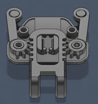
The mechanism utilizes two 20mm springs and the phone's own weight (gravity) to clamp the device firmly and securely in place, even on bumpy roads.
Technical Specifications
- Compatibility: Optimized for Skoda Octavia MK2. Fits phones up to 130mm wide (Tested and verified with Samsung Galaxy S23 Ultra and Galaxy S24).
- Mounting: Secure and stable CD-slot integration.
- Hardware Required:
- 4x M4x10mm screws (Main assembly)
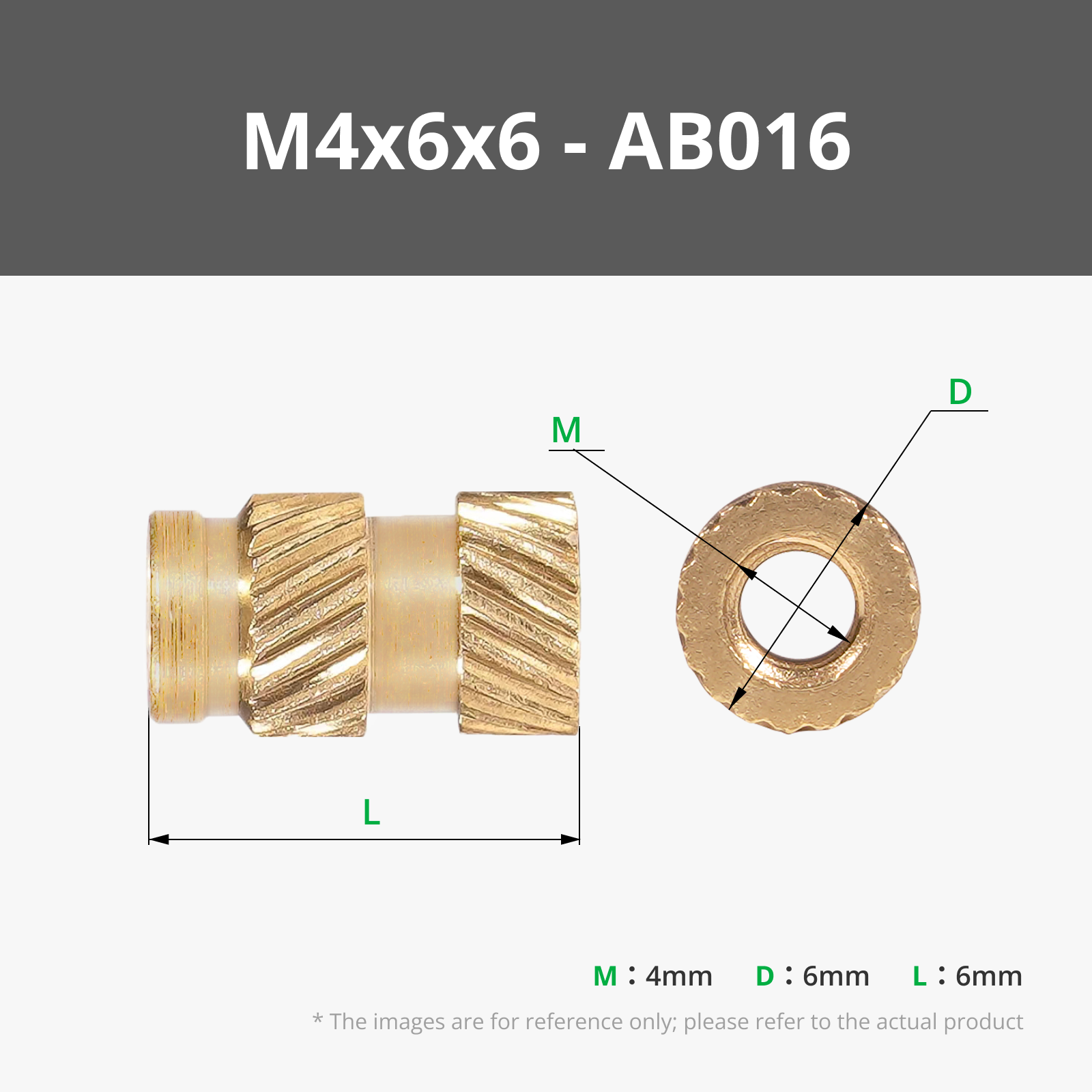
- 4x M4x6mm Threaded heat-set inserts
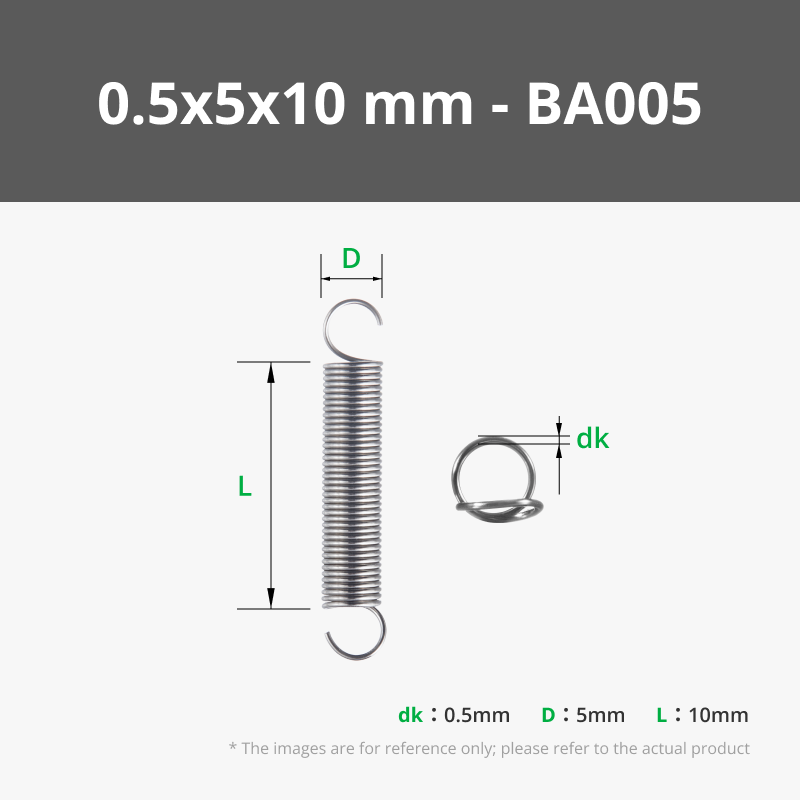
- 2x 20mm x 5mm Tension springs (To move the slider)
Print Settings & Recommendations
CRITICAL: Do NOT use PLA. Car interiors can reach temperatures over 70°C during summer, even in northern climates. PLA will soften and deform.
- Material: PETG (tested) or ASA/ABS.
- Walls: 5 Wall Loops recommended for all parts to ensure mechanical strength.
- Infill: 30% Gyroid.
- Supports: Optional/Not needed. Only recommended for the two holes in the CD-insert part.
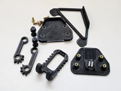
Assembly Instructions
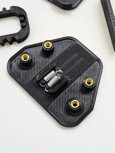
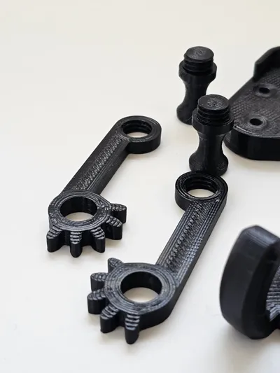
- Heat-set Inserts: Press the M4x6mm threaded inserts into the hollow pegs inside the main body.
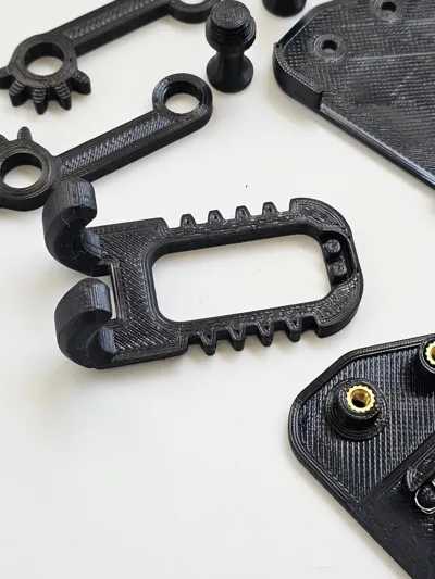
- Spring Installation: Attach the springs first to the Slider part, then hook the other ends onto the pegs in the main frame.
- Positioning: Place the Arms into their designated slots.
- Maintenance Tip: For the smoothest mechanical action, you can apply a small amount of silicone spray or lubricant to the moving parts.
- Closing the Frame: Place the Cover on top and secure it using the two lower M4x10mm screws.
- Final Step: Attach the CD Slot Mount part using the remaining two upper screws.
License
You shall not share, sub-license, sell, rent, host, transfer, or distribute in any way the digital or 3D printed versions of this object, nor any other derivative work of this object in its digital or physical format (including - but not limited to - remixes of this object, and hosting on other digital platforms). The objects may not be used without permission in any way whatsoever in which you charge money, or collect fees.
Comment & Rating (4)