Low Profile X2D,P2S External Fan V8


Print Profile(3)

Bill of Materials


- External Exhaust Air Filter - P2S Only x 1: https://us.store.bambulab.com/products/air-filter-for-external-exhaust-fan-kit
- External Exhaust Fan Kit - P2S Only x 1: https://us.store.bambulab.com/products/external-exhaust-fan-kit-p2s
Description
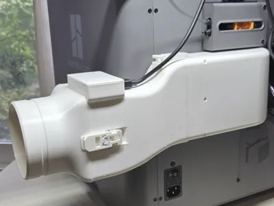
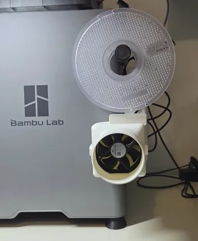
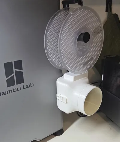
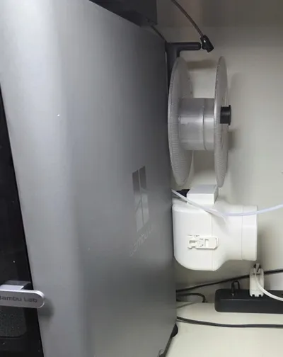
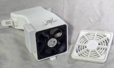
This model works with a X2D or a P2S, adding only 53mm to the depth of the printer, and it vents the printer to connect to a 3.75 inch diameter hose.
For the X2D, the fan, control board, air filter and hardware from the factory installed External Exhaust Fan can be reused for this model, but you will need to get some BT2x5 self-tapping screws (or equivlant) for the Latch pivots (listed in the Bill of Materials above).
For the P2S, it works with the components provided by the Bambu P2S External Exhaust Fan Kit and supports the External Exhaust Air Filter (listed in the Bill of Materials above).
Note: Before you order the External Exhaust Fan Kit from Bambu inspect the back of your printer. If there is no exhaust port on the back panel, then you have an early version of the printer and will need to order the External Exhaust Fan Kit + Rear Panel option from Bambu (which doesn't cost extra). And install the new rear panel before you can install the External Exhaust Fan upgrade. Instructions installing the rear panel are here.
NOTE: 3 output stage options are currently offered:
- Fan Grill - Print Plate 3, and DO NOT print Plate 2.
- 3.75 Inch OD hose adapter - Print Plate 2, and DO NOT print Plate 3.
- 75mm OD hose adapter - Use the “Low Profile Fan Vent P2S 75mm Hose Adapter” print profile to print it, and DO NOT print Plates 2 or 3 from the Low Profile Active P2S Fan Vent profile.
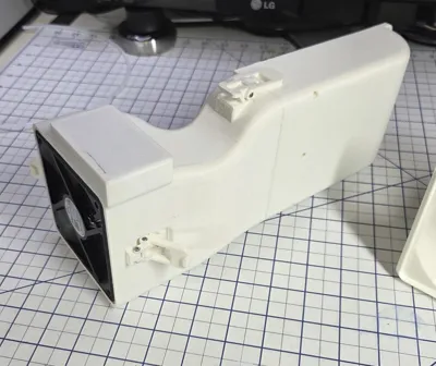
This model is divided into 3 parts: the Base Module, Fan Module, and Output Stage (Hose Adapter/Fan Grille). This partitioning allows easy modification of any component without needing to reprint the other components. For example, the Hose Adapter can be easily replaced to support different hose sizes. Let me know in the comments the Inner Diameter (ID) of the particular hose that you need.
Assembly
Base Assembly
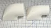
The first step is to assemble the Fan Vent Base. The two types of clips (as shown in Figure 1) are inserted into the Fan Vent Base (Low Profile Fan Vent P2S V4.stl) in the positions indicated in Figure 2.
Figure 1: Low Profile Fan Vent Clips

Be sure to orientate all the clips to point in the same direction, as indicated by the green arrow in Figure 2. Then insert the BT2x5 self-tapping screws, provided with the Bambu kit, from the opposite side (see the green arrows in Figure 12) and secure the Clips with the screws.
Figure 2: Base Clip Attachment

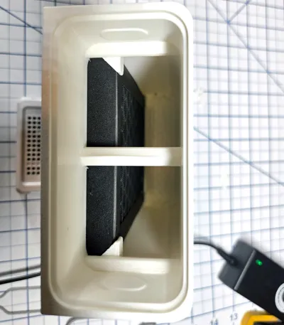
Finally apply the pre-cut black Foam Tape provided with the Bambu Kit to the Base. Confirm the correct position before pasting to avoid errors. Ensure the foam is aligned with the edge, and paste the four strips of top foam one by one as shown in Figure 2.
If you have an X2D and can't peel the tape of the factory fan cover, search for "1mm foam tape" on Amazon, they offer many options.
If available, insert the External Exhaust Air Filter as shown below.

Fan Module
The next step is to assemble the Fan Module.
Latches
Each Latch consists of two parts: Body and Latch.
First install the Latch Body part (Figure 3) on the fan Module connector, then insert two BT2x5 self-tapping screws as indicated by the green arrows and tighten them on the both sides to attach it to the Latch Body.
Note: The screws act as shafts. Do not over-tighten them, otherwise the Latch will not work smoothly.
Figure 3: Latch Body Installation

Next install the Latch Latch part (Figure 4) on the fan Module connector, then insert two BT2x5 self-tapping screws as indicated by the green arrows and tighten them on the both sides to attach it to the Latch Body.
Figure 4: Latch Body Installation

Now use the same process to attach the Latch components on the opposite of the Fan Module for the Base, and on the top and bottom of the Fan Module for the Hose Adapter, as shown in Figure 5.
Figure 5: Hose Adapter Latches

Fan Installation
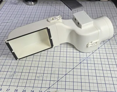
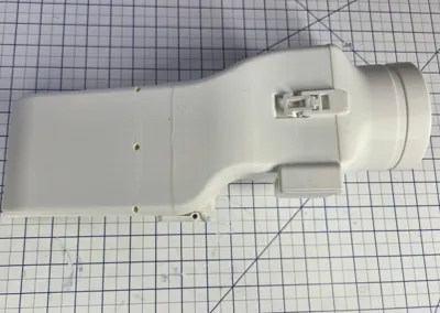
Before continuing remove any leftover support material from around the inside of the Connector Holes (Figure 6) and the ‘top’ inside surface of the PCB case (as indicated by the blue arrow in Figure 6). And ensure that PCB connectors fit through the holes, and the PCB fits snugly against the top surface of the PCB case.
Route the fan cable through the Fan Cable Hole as shown in Figure 6 and Figure 8.
Figure 6: PCB Case

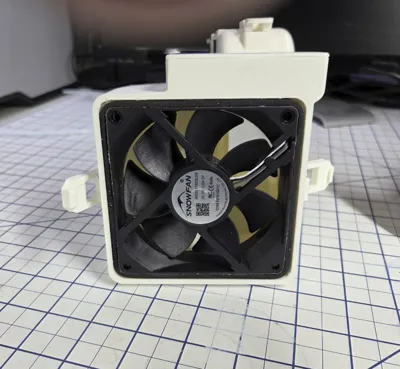
Then press the fan into the Fan Module with the orientation shown in Figure 7, while pulling on the fan cable. Note that the gasket that wraps around the fan is facing out. Also the airflow direction arrow on the side of the fan must be facing out as well. The surface of the fan should be flush with the surface of the fan module.
Figure 7: Fan Orientation

PCB Installation
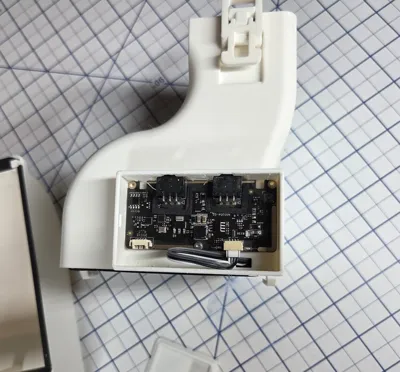
Connect the Fan Cable to the PCB then fit the connectors into the connector holes (Figure 6) and rotate the PCB so that it flat against the bottom of the PCB case. Finally use a BT2x5 self-tapping screw to secure the PCB to the Fan Module. Only one screw is necessary, because the left side of the PCB is held in place by its connectors.
Figure 8: PCB Installation

Now press the PCB Cover into the PCB Case. Make sure that the Connector Baffles (as shown in Figure 9) are over the connectors. Also make sure that there is no left over support material in the slots that the cover will clip into, otherwise it will not seat tightly.
Figure 9: PCB Cover

Output Stage
There are 3 Output Stage options:
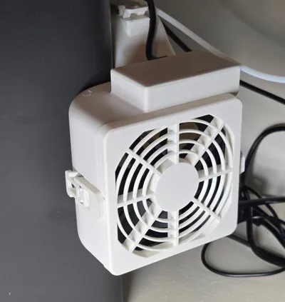
- Fan Grill
- 3.75 inch OD Hose Adapter
- 75mm OD Hose Adapter
The printing choices are discussed at the beginning of this Description, for the various options. Only print the Plate associated with the option that you choose!
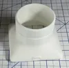
For all 3 options, you will need to press the Hose Adapter Gasket into the Hose Adapter Module so that it seats as show in Figure 10a.
Note: There may be some elephant foot around the outside edge of the gasket, scrape it if necessary to allow the gasket to be pressed into the Hose Adapter. Also, one end of the gasket is chamfered on both edges. The chamfered edges should be facing out when inserted. The Gasket is printed with the chamfered edges facing up.
Figure 10a: Hose Adapter

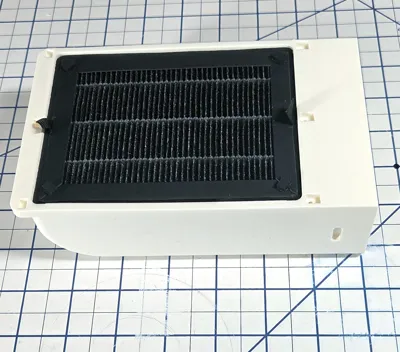
Fan Grill
Similar to the Hose Adapter (Figure 10a), press the Hose Adapter Gasket into the Fan Grille so that it seats as show in Figure 10b.
Note: There may be some elephant foot around the outside edge of the gasket, scrape it if necessary to allow the gasket to be pressed into the Fan Grille. Also, one end of the gasket is chamfered on both edges. The chamfered edges should be facing out when inserted. The Gasket is printed with the chamfered edges facing up.
Figure 10b: Fan Grille

Right Angle Hose Adapters
Similar to the Hose Adapter (Figure 10a), press the Hose Adapter Gasket into the Right Angle Hose Adapter so that it seats as show in Figure 10a.
Note: There may be some elephant foot around the outside edge of the gasket, scrape it if necessary to allow the gasket to be pressed into the Right Angle Adapters. Also, one end of the gasket is chamfered on both edges. The chamfered edges should be facing out when inserted. The Gasket is printed with the chamfered edges facing up.
Figure 10b: 3.75inch and 75mm Right Angle Hose Adapters

The Right Angle Hose Adapters can be attached with the hose facing up, down, forward, or backwards.
Figure 10c - Installed Right Angle Hose 75mm Adapter, facing up

The Low Profile Fan Vent P2S X2D Rt Angle Hose Adapters Vx.3MF file includes two versions of the 3.75 inch and 75mm adapters: One with normal Tree supports and the other using tree supports and PETG as an interface layer. I added the PETG versions, which add about 3.5 hours to the print time, to see if they would signicantly inprove the surface quality. I didn't see a improvement that I was hoping for, especically considering the additional print time, but I left them in the file.
Final Installation
If attached, tear off the sticker on the printer’s rear panel exhaust port. If there is no exhaust port on the back panel, they you will need to order the “External Exhaust Fan Kit + Rear Panel” option from Bambu.
Figure 11: Sticker Removal

Base Module
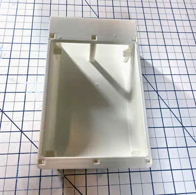
Hold the Base Module and align the clips with the slots on the rear panel. Press the Base Module firmly against the rear panel to compress the foam gasket, then slide it to the left (as indicated by the red dashed arrow). You should feel the module snap into place to the preset installation position of the rear panel.
The green arrows indicate where the BT2x5 self-tapping screws are inserted to secure the clips.
Figure 12: Base Module Installation

Fan Module
Fit the Fan Module to the Base Module, then use the top and bottom latches to secure it in place.
After installation, connect the 6PIN cable between the fan connector to the corresponding connector of the buffer.
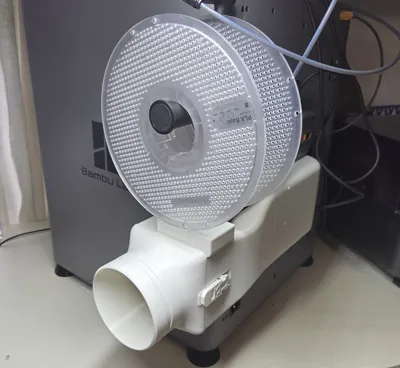
Note that the Fan Module wraps around the P2S case, further locking the Base into position when attached.
Figure 13: Fan Module Installation
Hose Adapter
Finally fit the Hose Adapter to the Fan Module, then use the front and back latches to secure it in place.
Figure 14: Hose Adapter Installation

Two Hose Adapters are supported; 3.75 inch and 75mm. If you want to use the 75mm, don't print the 3.75 inch hose adapter in the main “Low Profile Active P2S Fan Vent V4” profile, and print the one in the Low Profile Fan Vent P2S 75mm Hose Adapter V2 profile.
Figure 15: Hose Adapter options: 3.75 inch and 75mm

And as always, if this design proves useful to you please boost me.
Revisions:
V1 - Initial release
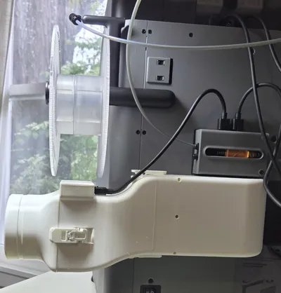
V2 - Dropped down output of Fan Module 25mm so it does not interfere with the operation of the external spool.
V3 4/29/26 - Added support to Base Module for the External Exhaust Air Filter.
V4 4/30/26 - Added a Fan Grille.
V5 5/14/26 - Added a “Low Profile Fan Vent P2S 75mm Hose Adapter V2” print profile for a 75mm Hose Adapter that is compatible with the Low Profile X2D,P2S External Fan design. It can be substituted for the 3.75 inch Hose Adapter included in the base profile.
V6 5/25/26 - Fixed zero thickness wall depth defect in Fan Module.
V7 6/16/26 - Added 3.75 inch and 75mm Right Angle Hose Adapters.
V8 7/15/26 - Relaxed tolerances on the Adapter Gasket so it is easier to insert.
Print Low Profile Active P2S Fan Vent Vx.3mf, Plate 1 and, depending on your choice:
- Low Profile Active P2S Fan Vent Vx.3mf, Plate 2 - 3.75 inch hose adapter
- Low Profile Active P2S Fan Vent Vx.3mf, Plate 3 - Fan Grille
- Low Profile Fan Vent P2S 75mm Hose Adapter Vx.3MF, Plate 1 - 75mm hose adapter
- Low Profile Fan Vent P2S X2D Rt Angle Hose Adapters Vx.3MF, Plate 1 or 3 - 3.75 inch adapter
- Low Profile Fan Vent P2S X2D Rt Angle Hose Adapters Vx.3MF, Plate 2 or 4 - 75mm adapter
Low Profile Active P2S Fan Vent Vx.3MF Plates:
Plate 1) - Body, Fan Module, Clips, Latches, and PCB Cover.
Plate 2) - 3.75 inch hose adapter.
Plate 3) - Fan Grille.
Low Profile Fan Vent P2S 75mm Hose Adapter Vx.3MF Plates:
Plate 1) - 75mm Hose Adapter.
Low Profile Fan Vent P2S X2D Rt Angle Hose Adapters Vx.3MF Plates:
Plate 1) - 3.75 inch Right Angle Hose Adapter - Tree supports.
Plate 2) - 75mm Right Angle Hose Adapter - Tree supports.
Plate 3) - 3.75 inch Right Angle Hose Adapter - Tree supports, w/ PETG interface.
Plate 4) - 75mm Right Angle Hose Adapter - Tree supports, w/ PETG interface.
Comment & Rating (126)