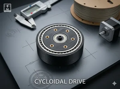
Cycloidal Drive 1:20


Print Profile(1)
Description
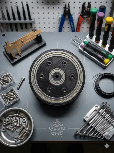
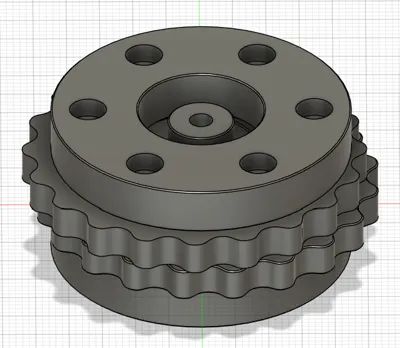
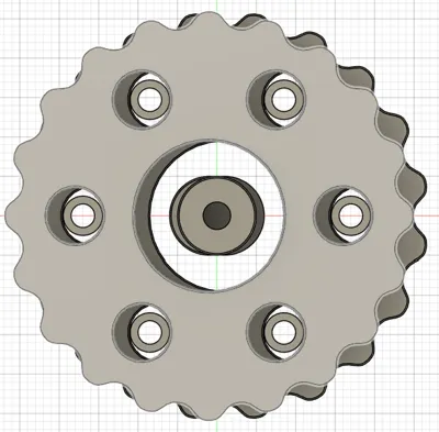
3D Printed Cycloidal Gearbox – Detailed Assembly Guide
Overview
This project is a fully 3D printed cycloidal gearbox designed for compactness, durability, and smooth torque transmission. The design utilizes standard hardware components such as M3 screws, threaded inserts, and ball bearings to ensure structural rigidity and reliable operation.
Gear ratio: 1:20, making this gearbox ideal for applications requiring high torque and reduced output speed.
The gearbox is optimized for makers who want a precise and robust reduction mechanism using accessible components and additive manufacturing.
Required Components
Hardware
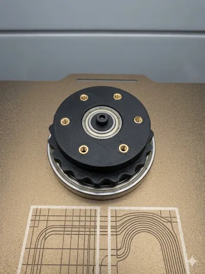
- 6× threaded inserts (for the output ring)
- 2× threaded inserts (for the shaft)
- M3 screws (length: 20 mm)
- 3D printed spacers (bushings) for M3 screws
Bearings
- 4× ball bearings (10 × 19 × 5 mm) – mounted on the shaft
- 2× ball bearings (45 × 58 × 7 mm) – mounted in the outer ring
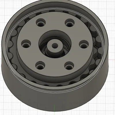
3D Printed Parts
- Cycloidal disc(s)
- Output ring
- Outer housing
- Shaft
- Spacers (bushings)
Assembly Instructions
1. Install Threaded Inserts
- Insert 6 threaded inserts into the designated holes in the output ring.
- Insert 2 threaded inserts into the shaft.
- Use a soldering iron or heat-set tool to ensure proper seating and alignment.
2. Prepare the Shaft Assembly
- Slide 4 bearings (10×19×5 mm) onto the shaft.
- Ensure they are evenly spaced according to the design.
- Bearings should rotate freely without binding.
3. Assemble the Outer Ring
- Press-fit or carefully seat 2 large bearings (45×58×7 mm) into the outer ring.
- Make sure they are fully seated and aligned to avoid wobble.
4. Install Spacers and Screws
- Take the M3 × 20 mm screws and place the 3D printed spacers onto them.
- Insert the screws with spacers into the appropriate holes in the cycloidal mechanism.
- The spacers act as rollers or guides—ensure smooth rotation after installation.
5. Mount the Cycloidal Disc
- Position the cycloidal disc inside the outer ring.
- Align it with the shaft and eccentric motion system (depending on your design).
- Carefully rotate to confirm proper engagement with the pins/spacers.
6. Final Assembly
- Insert the shaft assembly into the housing.
- Align all components:
- Shaft bearings
- Cycloidal disc
- Output ring
- Secure everything using the M3 screws threaded into the inserts.
Final Checks
- Rotate the input shaft manually:
- Movement should be smooth and consistent
- No binding or excessive friction
- Verify that:
- Bearings are seated properly
- Screws are tightened but not overtightened
- Spacers rotate freely
Notes & Tips
- Use high-quality filament (e.g., PETG, ABS, or Nylon) for better durability.
- Ensure tight tolerances for bearing seats.
- Lubrication (light grease) can significantly improve performance and lifespan.
- Check alignment carefully—cycloidal gear systems are sensitive to misalignment.
Applications
This gearbox is suitable for:
- Robotics
- CNC mechanisms
- Actuators
- High-torque low-speed applications
Enjoy building and experimenting with your 3D printed cycloidal gearbox!
License
You shall not share, sub-license, sell, rent, host, transfer, or distribute in any way the digital or 3D printed versions of this object, nor any other derivative work of this object in its digital or physical format (including - but not limited to - remixes of this object, and hosting on other digital platforms). The objects may not be used without permission in any way whatsoever in which you charge money, or collect fees.
Comment & Rating (3)