
AH 64D Apache MPD (for DCS)
Print Profile(1)
Description
Glad you're checking out this project. Hope you like it!
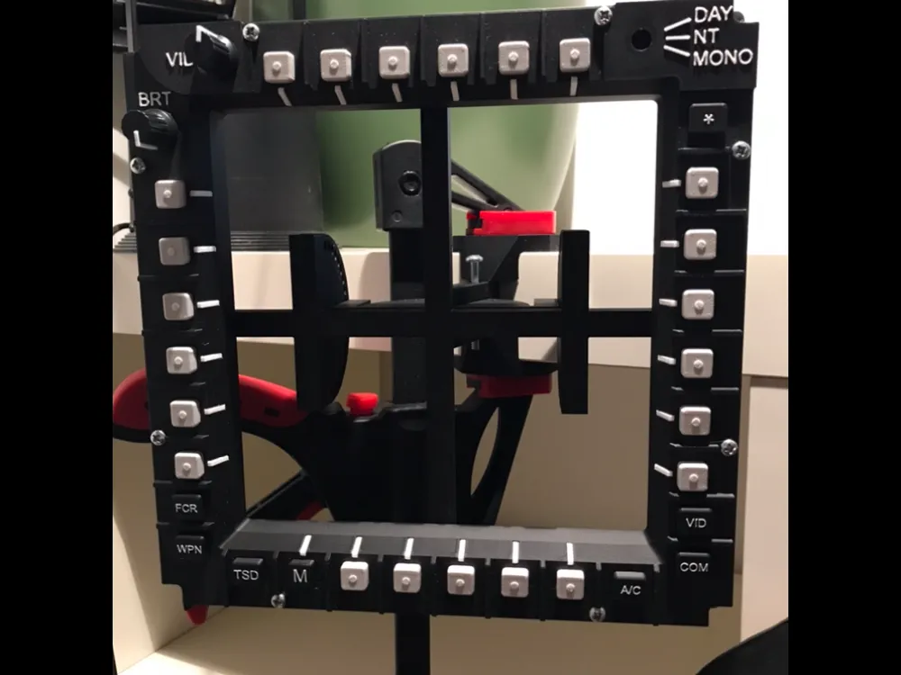
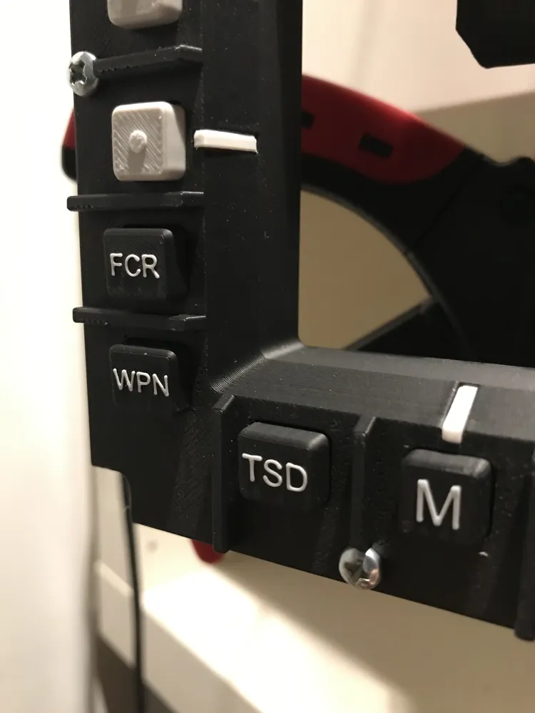
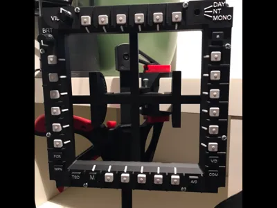
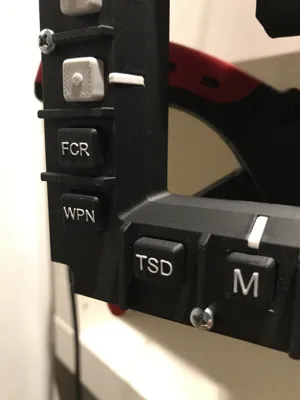
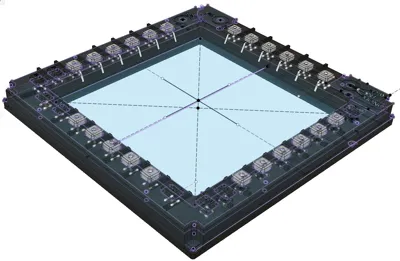
This model is a detailed replica of an MPD (Multi-Purpose Display) panel from the AH-64 Apache and was specifically developed for use in DCS. A particular focus was on the simplest possible implementation: by using an I2C system and the provided code, the panel can be used almost Plug & Play after a one-time setup – no programming knowledge is required.
Assembly and wiring require some patience and careful work, but are also well manageable for beginners:
The holder in the picture is currently still in the refinement phase, but will follow soon.
A 0.2mm nozzle is needed to print the "special buttons" with inscriptions (if desired). Alternatively, a version without inscription can also be printed, and the inscription printed on paper and then glued on (see documentation (available upon request) ).
What is needed
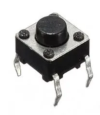
- 31 simple buttons (quite cheap 100 pieces about 5 Euros, Link Here)
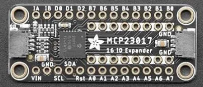
- 2 Adafruit MCP23017(s) (Link HERE)
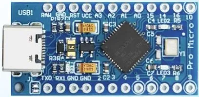
- 1 Arduino Pro Micro (Link HERE)
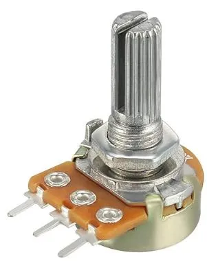
- 8 M3 screws (max. width 6mm, min. length 16mm, max length 21mm)
- many thin wires
Assembly
1.
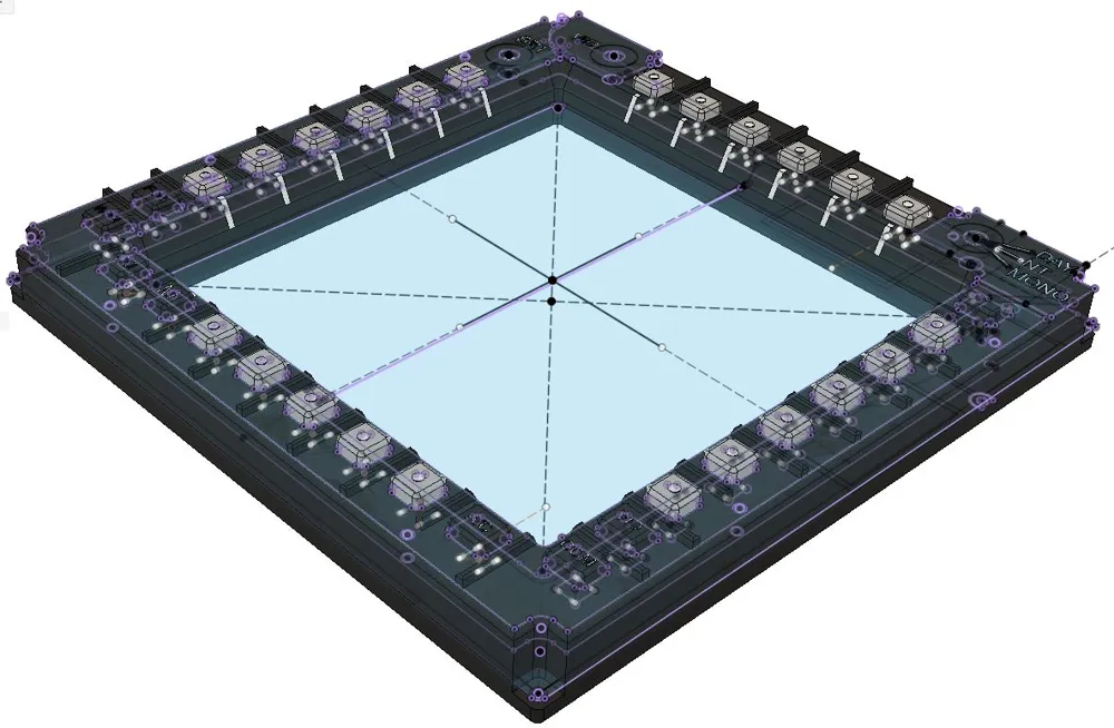
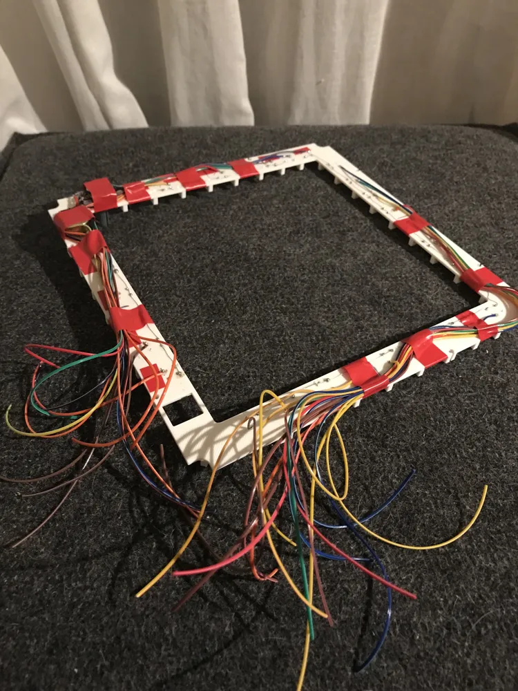
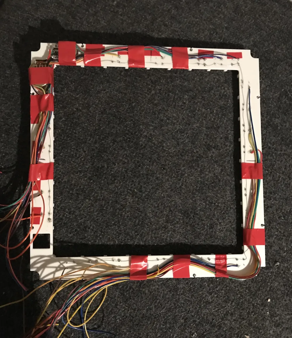
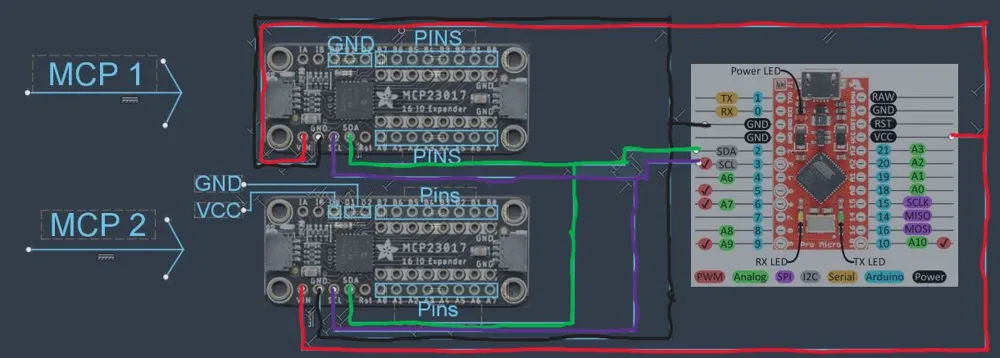
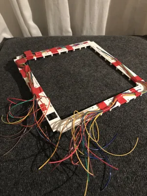
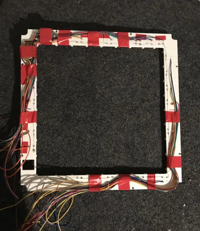
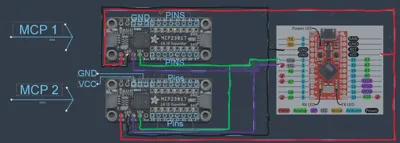
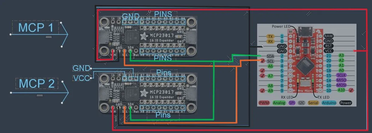
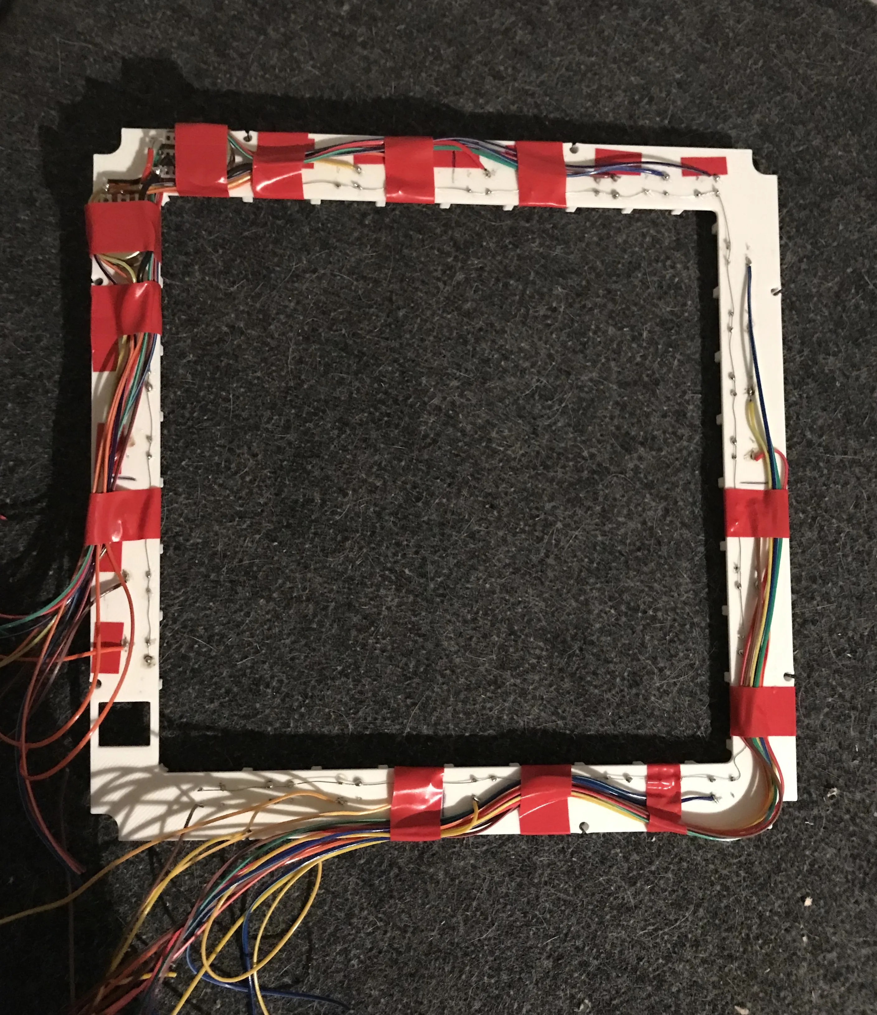
Print Print Plate 2 and insert the buttons and potentiometers. Then wire everything as shown in Picture 1 (Here, nothing needs to be wired to Arduino or MCPs yet; it's just about having one end already wired). Black means GND and Blue means it will be wired to Arduino or MCPs (see Picture 2 Pins field) (Positions in the Blue Field don't matter). ATTENTION: for the potentiometers, the middle pin is the signal pin and is not connected to an MCP, but to Pin A0/A1 of the Arduino. Furthermore, the GND on a potentiometer is connected to the left output (picture above), i.e., the one with the holder whatever, and VCC to the right output (red marked Picture 1). In Picture 2, fields of MCPs 1/2 are labeled with GND and/or VCC; GND/VCC also needs to be routed here (VCC and VIN are the same).
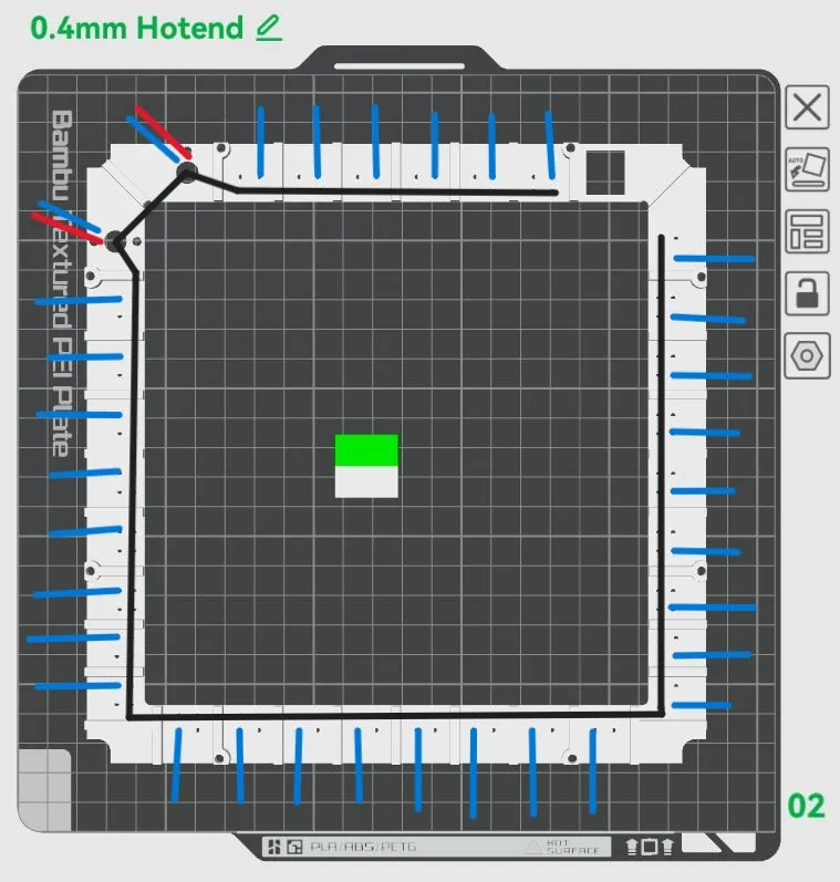
2.
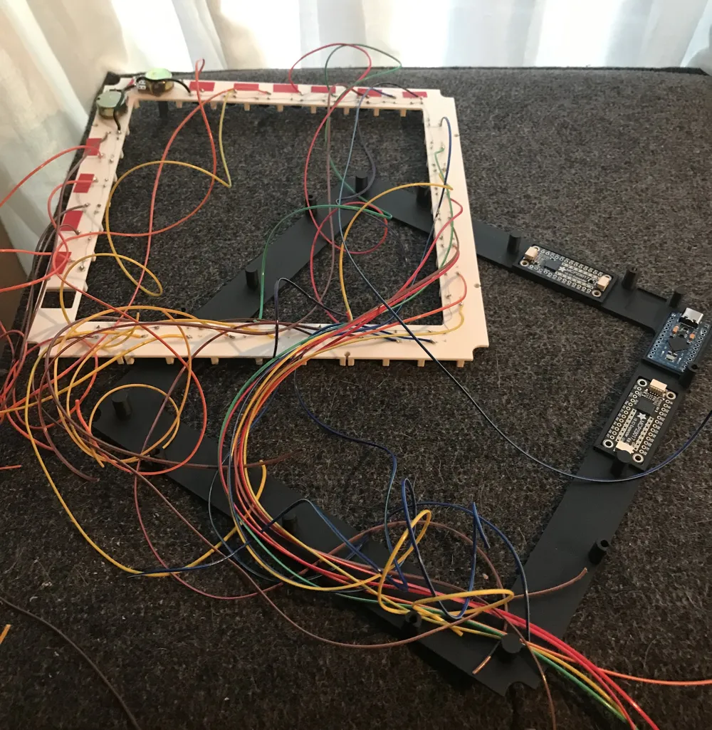
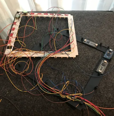
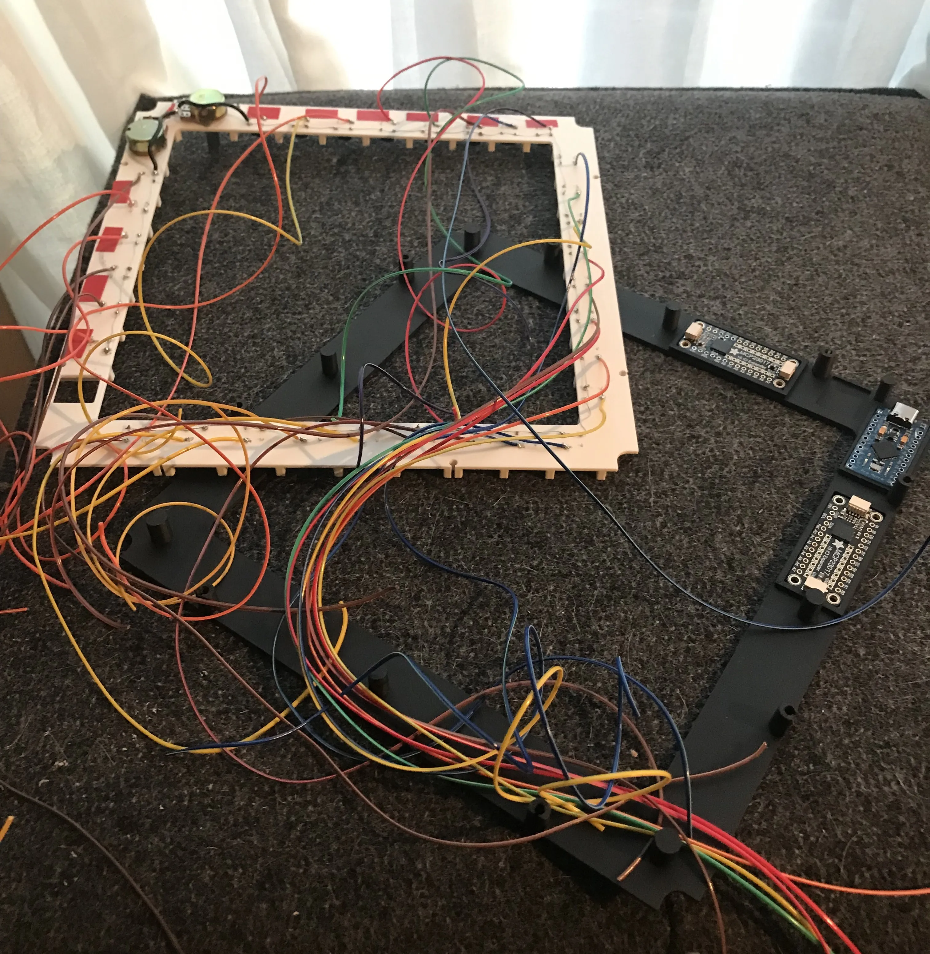
Print Plate 3. You can now place the previous part on the part from the 3rd print plate to better estimate the distance to the MCPs / Arduino (it must not be too long, otherwise it will be very very veeeery difficult to squeeze it into the frame later, but also not too short). Then you can wire it. (as seen in Picture 2)
Next, I would first do a test to see if everything works. To do this, simply copy the code (see documentation) from the .txt file and upload it to the Arduino using a program of your choice. ATTENTION, 2 libraries are needed, namely
Joystick @^2.1.1 from mheironimus
Adafruit MCP23017 Arduino Library @^2.3.2 from adafruit
I could not find the Joystick Library in Arduino IDE, which is why I used VS Code.
(If you don't know how to do it, there are thousands of videos about it on YouTube, so I won't explain it further here.)
e.g.
https://www.youtube.com/watch?v=gQ2lsSuXvVU for installation and code
https://www.youtube.com/watch?v=_pSVzV4PdiA for adding libraries
once the code is on the Arduino, unplug the cable from the Arduino and plug it back in; it didn't work for me without doing that. Then open the search bar and search for "Set up USB game controllers". An "Arduino Micro" device should now appear there. If not, it could be because the cable you are using is a charge-only cable and cannot transmit data, or something in the code / wiring is faulty. If every button and potentiometer works correctly, you can proceed to the next step.
4.
Now you can print the buttons (different plate depending on whether you use a 0.2 nozzle or not), the frame (Plate 1) and the parts on Print Plate 4 and insert them into the correct positions in the frame. Next, we want to assemble all parts, but first I would advise you to place the parts from Print Plate 2/3 on top of each other and glue them together. I used some Scotch tape for this. What is also very important is to attach the Arduino to the part of Plate 3; for this, I again used Scotch tape. And then you can assemble it and screw it together with the 8 screws from the front.
„MPD online. Systems ready.“
Here are a few more pictures of my wiring
Plans
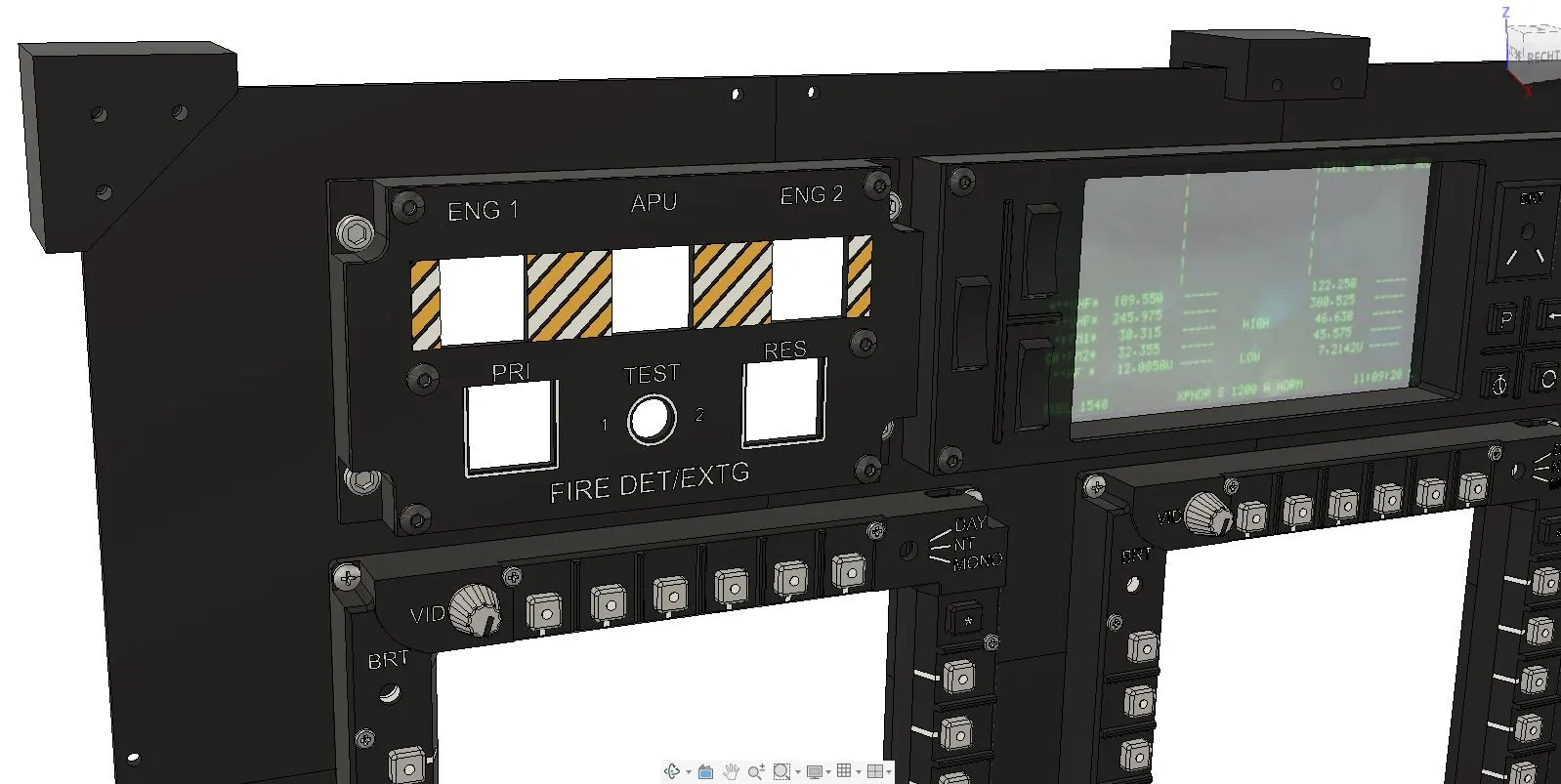
Currently, I am working on a holder for the MPD, which should allow it to be easily attached to a table edge. I am also working on other panels for the Apache
Boost Me (for free)
If you like this Apache MPD and want to support my work, you can do so via the Boost-me badge. A Boost helps me to implement more cockpit modules, new variants, and future DCS projects. Any support is voluntary, highly appreciated, and motivates me to continue improving and expanding the models.
Thank you for viewing, printing, and sharing this model! 🚁
Documentation (1)
License

You shall not share, sub-license, sell, rent, host, transfer, or distribute in any way the digital or 3D printed versions of this object, nor any other derivative work of this object in its digital or physical format (including - but not limited to - remixes of this object, and hosting on other digital platforms). The objects may not be used without permission in any way whatsoever in which you charge money, or collect fees.


Comment & Rating (0)