
P2S active chamber heater with HEPA/Carbon filter
Print Profile(1)
Description
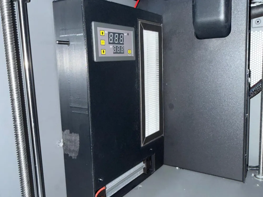
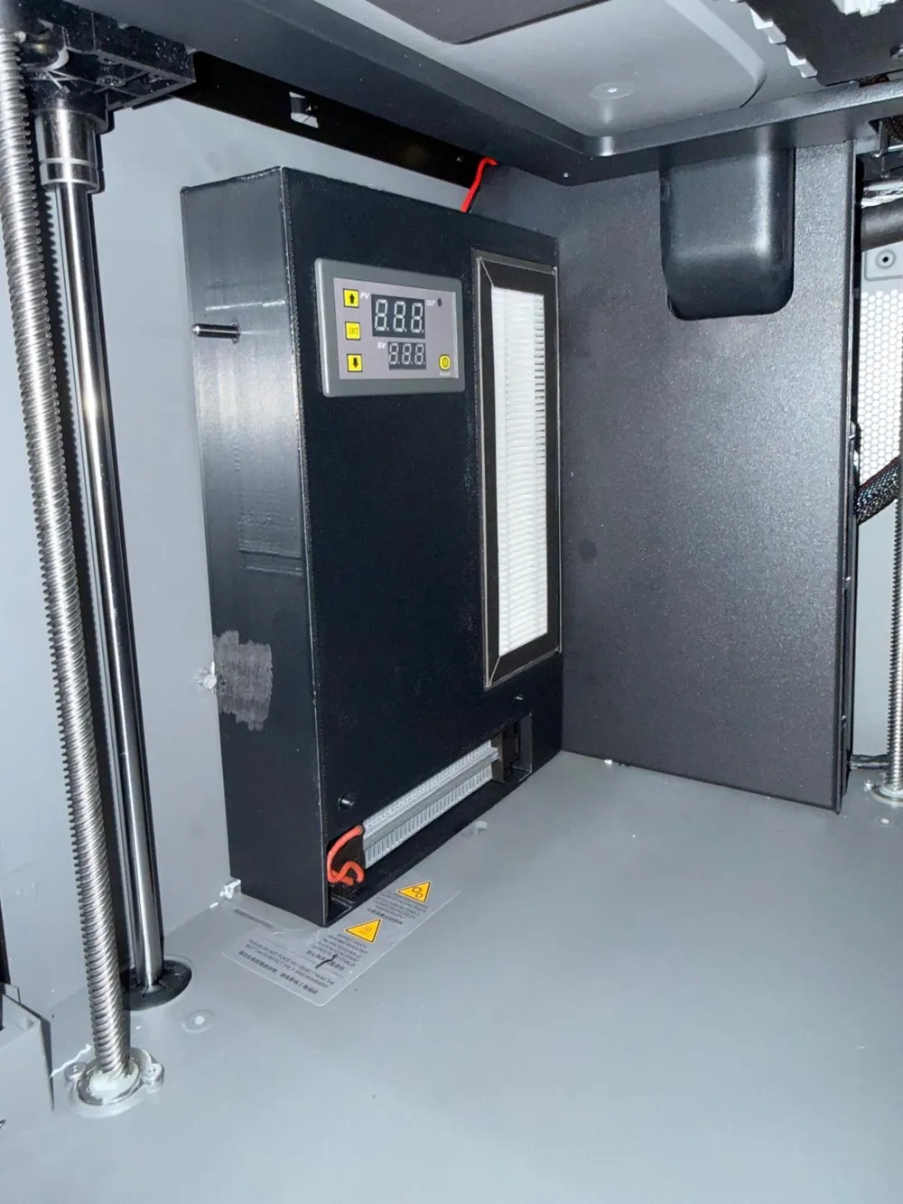
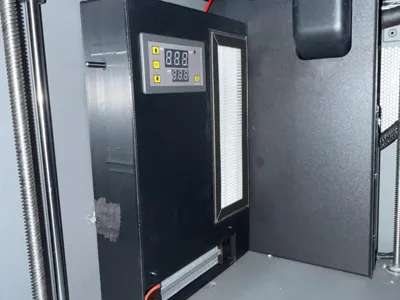
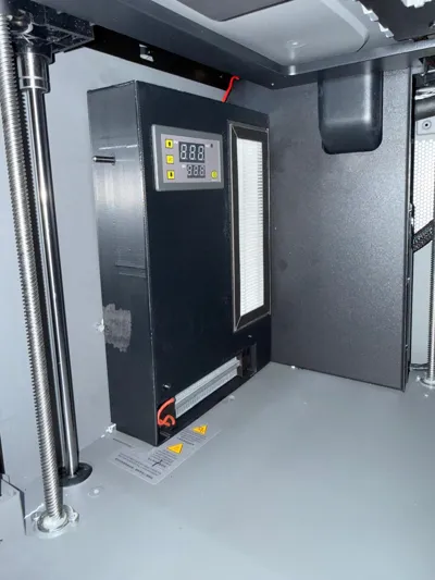
P2S active chamber heater with HEPA/carbon filter.
After long time searching for alternatives that did not fully comply with what I wanted, I dedided to create my own chamber heater for the P2S. And it works!
The print is divided in two parts. One is the base and other the lid.
All the components are placed in the lid.
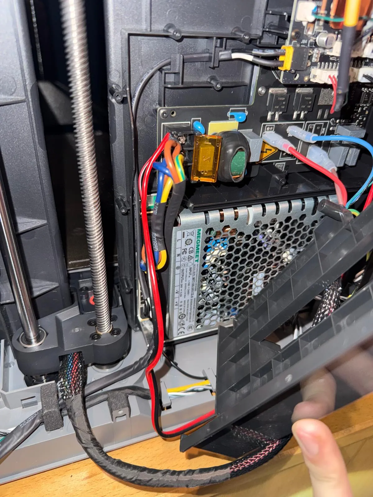
All components are 220v and are connected to the printer in the entrance side of the PSU, so there is no extra load for it.
The timer relay is meant to maintain the fan working for a little longer than the heater itself. In order to cool it down and continue filtering. But it can be removed if not deemed necessary.
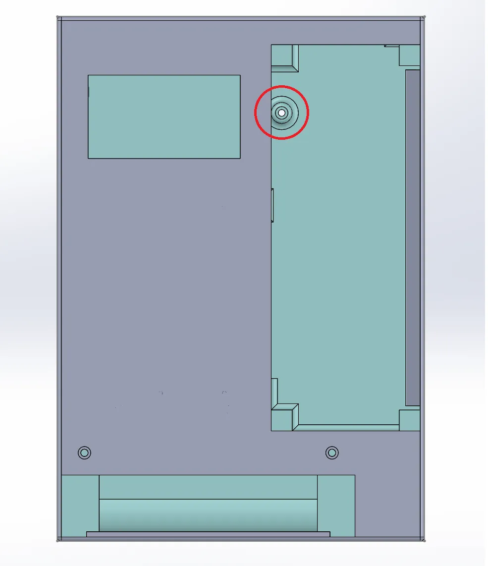
The base has several holes and cuts to fit exactly into the P2S side panel. The intention is that you use this screw to attach it to the printer. Although double sided tape or even just standing works perfectly.
For the assembly you'll need the following items:
110/220v digital temperature controller
Cables for PSU. I used THIS in 16AWG.
10 x M3 screws 6mm long. I used THIS
10 x M3 inserts for the locking screws and the timer relay mounting.
The (very rudimentary) schematic is the following:
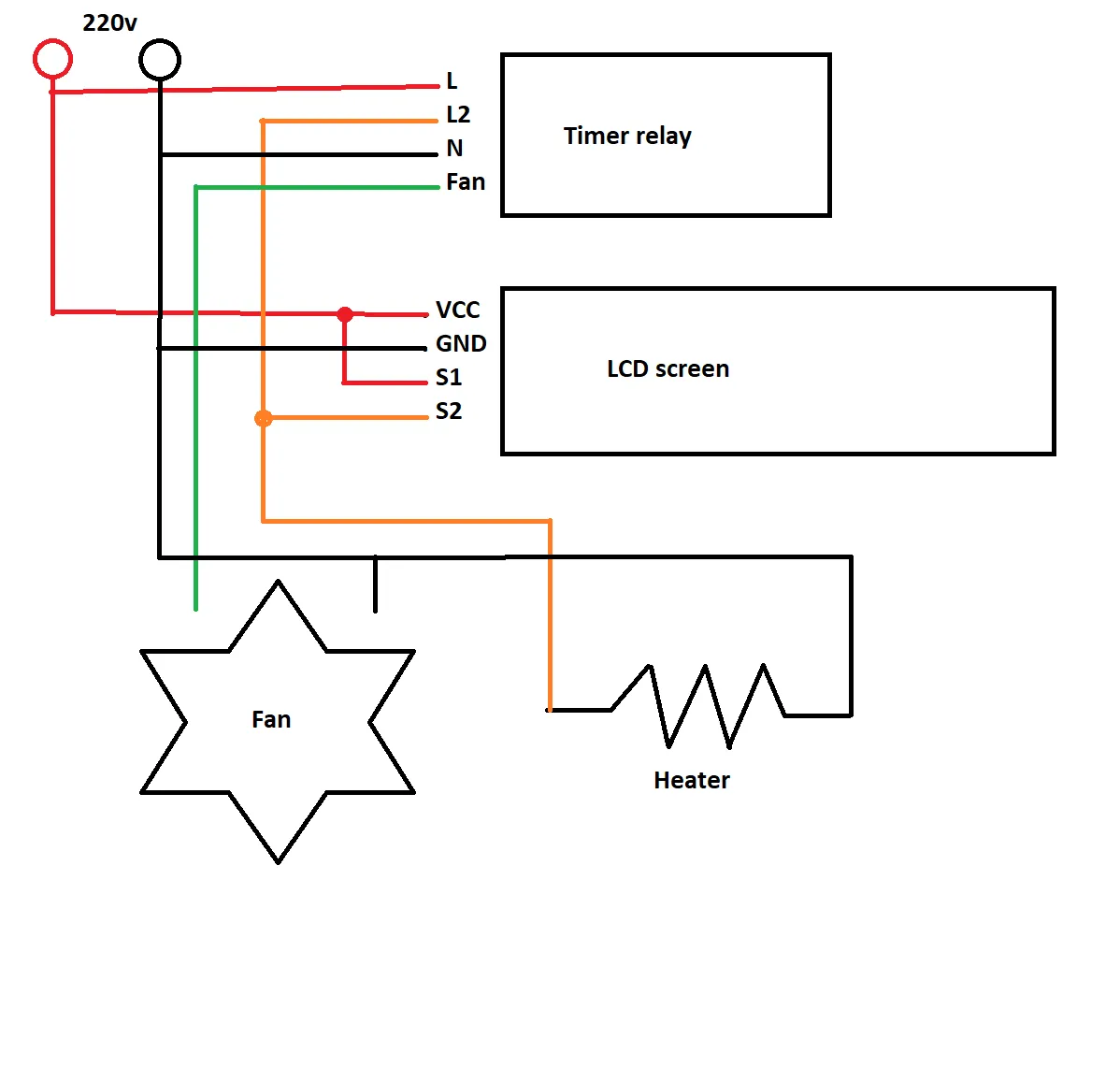
I did not take many photos of the assembly process but it is very straightforward. There are some cables that need routing according to the next image.
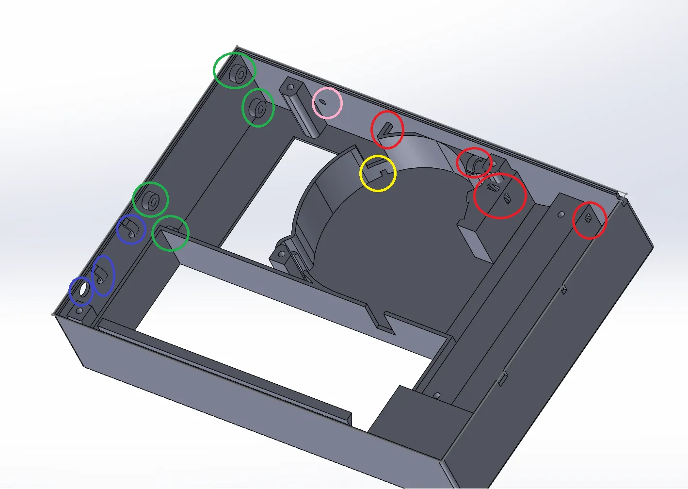
Red circles are the passages for the heater cables.
Yellow circle is for the fan cables.
Pink circle is for the temperature sensor.
Green circles are for the timer relay mounting.
Blue circles are for the 220v cable to the printer PSU.
The heater itself is only placed where it belongs and then pressed in position with the backplate. No screws needed.
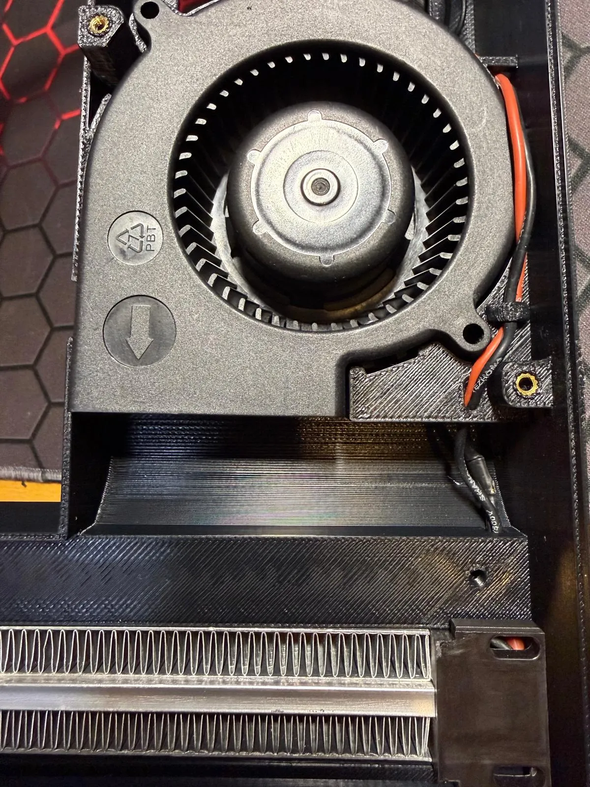
Heated with cables mounted:
Connection to the back of the printer, PSU:
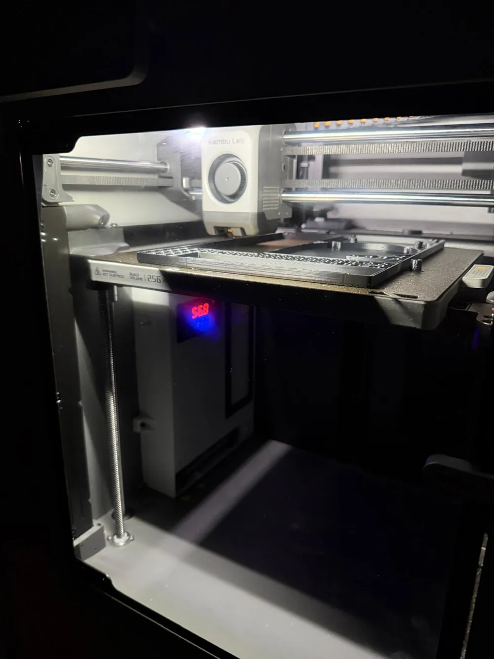
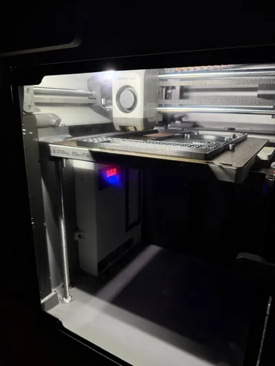
Final assembly and working:
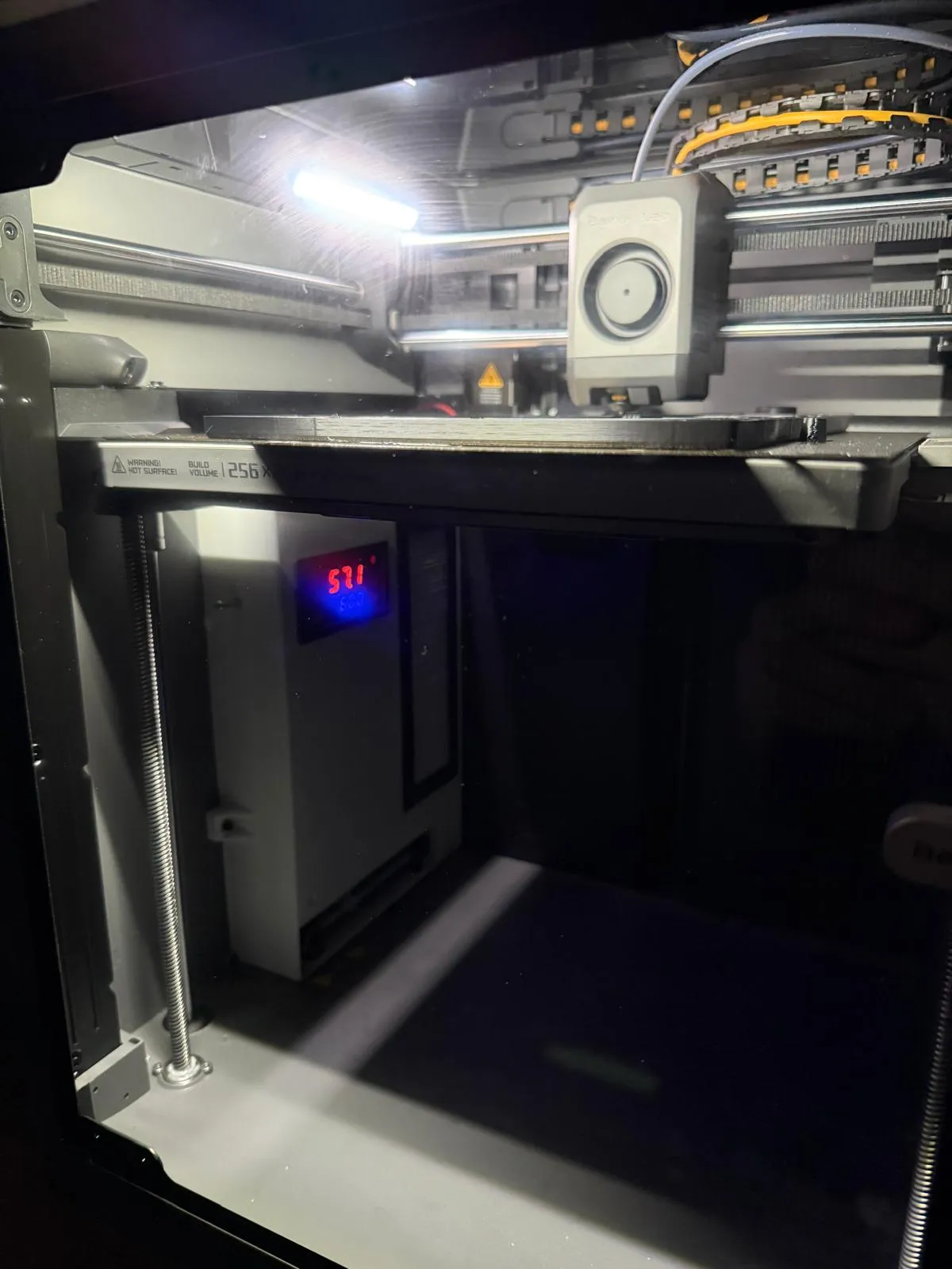
In the previous photo, a side screw can be seen. This was removed because it was not really necessary.
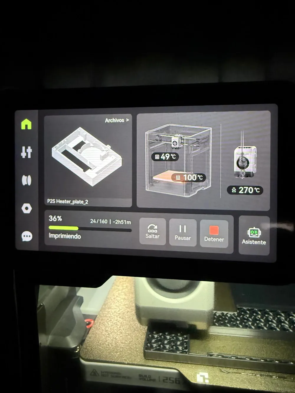
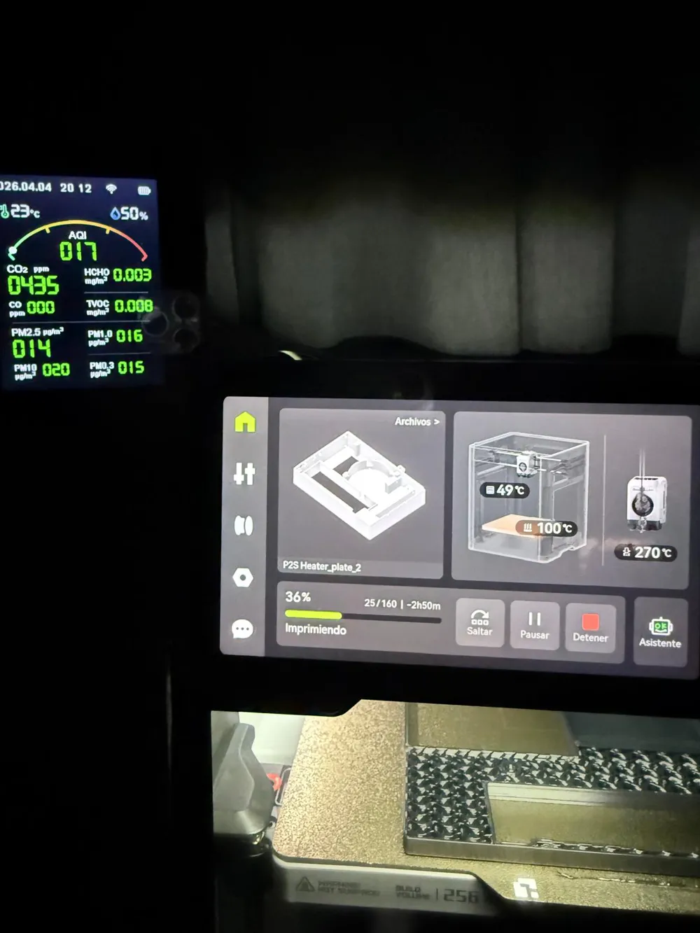
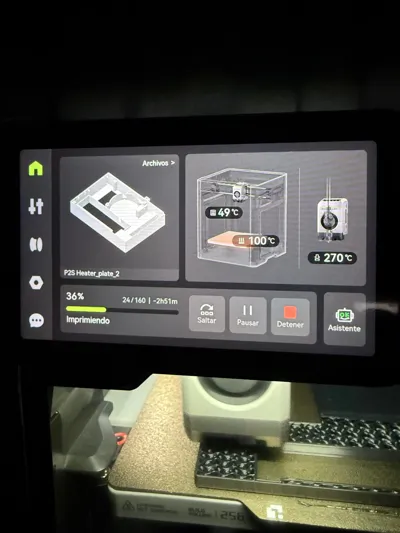
Temperature reaches around 55°C according to the heater, around 50°C according to the printer. All this with no other mods.
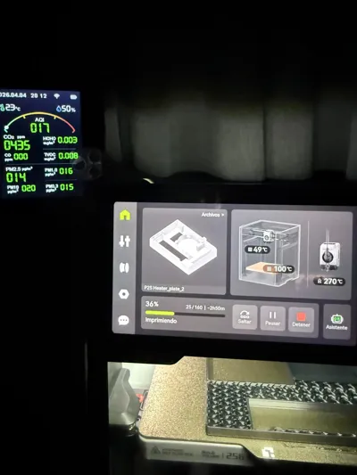
The air quality monitor while printing ASA shows all good values, proving that the filtering works fine.
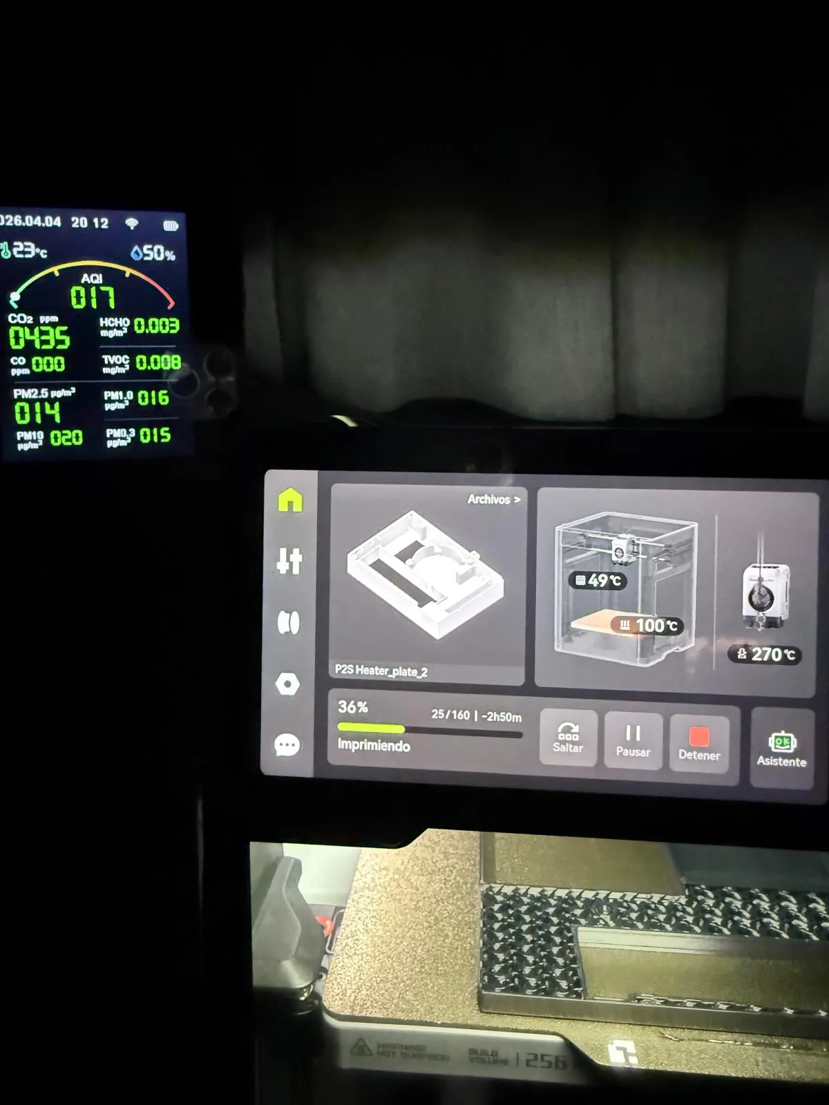
As you will probably notice, I am not a designer, but I did my best.
You are welcome to print it, modify and fork it.
License



Comment & Rating (12)