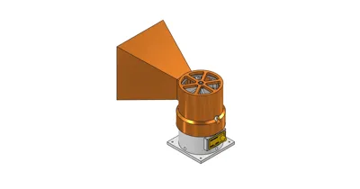
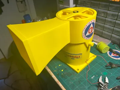
Thunderbolt V3 Siren


Print Profile(1)
Description
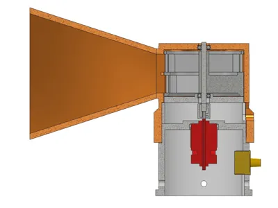
Based on the Mini Thunderbolt Siren by J0hn Bingus. This siren has been totally reimagined. It all started with the rotor correcting modeling issue and deciding to put a solid metal shaft through it. From there the only other design element retained was the outlet opening size and the use of pins to hold the horn on. The stator housing diameter has been adjsuted to tighten the gap between the rotor and stator to .5mm to increase efficeny.
From there I utilized a keys to align the models various parts together. This is a close tolerance model. My Bambu X1C has no adjustments to compensate for scaling xy or z and printed this jsut fine and everything fit together snug. The rotor shaft I planned on adding epoxy into the splined hole before inserting the shaft, however the shaft fit snug enough it was not needed.
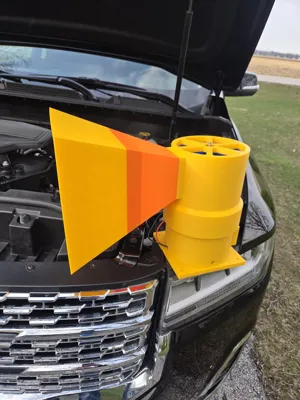
Please be aware this model excluding the rotor will use a full 1KG of filament. I ran out and used up some low spools on the horn ;)
Video in action:
All purchased parts came from Amazon.
Preffered coupler: https://www.amazon.com/dp/B08QV7SVH7?ref=ppx_yo2ov_dt_b_fed_asin_title&th=1
Speed Controller: https://www.amazon.com/dp/B0B393M4PS?ref=ppx_yo2ov_dt_b_fed_asin_title
Rotor Shaft: https://www.amazon.com/dp/B0BNL4VVW4?ref=ppx_yo2ov_dt_b_fed_asin_title&th=1
Motor: https://www.amazon.com/dp/B0BW73N4VN?ref=ppx_yo2ov_dt_b_fed_asin_title&th=1
The Design will allow for other couplers. I was going to do this rigid but I didnt want any bind and went to the spider type: https://www.amazon.com/dp/B0CH9MDR2G?ref=ppx_yo2ov_dt_b_fed_asin_title&th=1
You will also need two 608 type bearings, dealers choice here… 8mm X 22mm x 7mm.
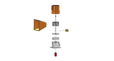
Assembly:
- Press bearings into each respective place. Ensure they are all the way to the back and in straight.
- Cut the linear shaft to 115mm length, chamfer the cut end.
- Drive linear shaft into rotor, using calipers measure the part extending out of the rotor that has a chamfer, set this length to no more than 30.2mm, prefferably 30. This side of the rotor is the flat side, the top has a hub.
- Insert the thin spacer on the bottom/measured side of the rotor shaft.
- Insert the thick spacer on the other end.
- Install rotor into the housing.
- Install the bearing plate into the housing, use the bottom grooves to help align this. This is a tight fit.
- Install motor into housing.
- Install coupling onto motor, ensure motor shaft does not extend into the 8mm shaft spot.
- Put spacer into housing, align slot so you can tighten coupler.
- Place the motor housing into the rotor housing aligning to the keys. This will sandwhich the spacer. Endusre this is compressed as much as possible.
- Tighten the coupler thru the slot.
- Wire up the motor to the speed cotroller and extend your lead wires.
Comment & Rating (25)