G-SCALE WARREN BRIDGE - MODULAR SYSTEM


Print Profile(1)
Description
Assembly and Printing Instructions
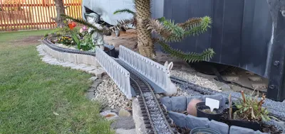
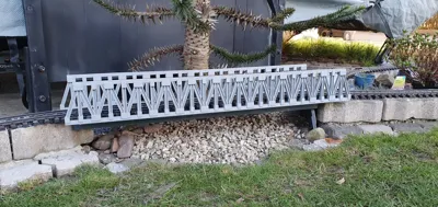
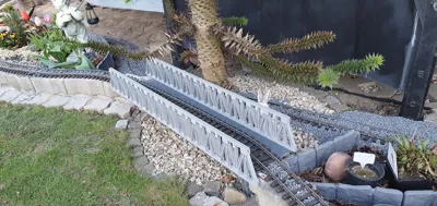
🚂 G-Scale Warren Truss Bridge – Modular Snap-Fit System
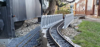
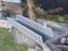
This highly detailed, parametric truss bridge for garden railways (G-Scale / 45mm) is designed as a robust, modular kit. Thanks to the intelligent Snap-Fit System, it can be assembled with extreme stability and almost entirely without glue. New Update: The bridge ends are realistically optimized for abutments (foundations) – the lower outer gusset plates are completely solid so the bridge rests perfectly flat on your masonry or concrete!
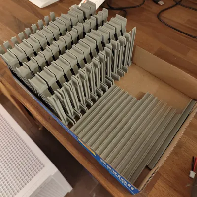
🛠️ Step 1: Part Export from OpenSCAD
Please do not load the complete view into the slicer! The model uses OpenSCAD as a "parts factory".
- Open the .scad file in OpenSCAD.
- In the right-hand menu under [Display & Print Options], select the desired individual part from the dropdown menu (e.g., middle_piece).
- Press F6 (Render) and then F7 (export as STL).
- Repeat this for all required building blocks:
- End pieces (Left/Right)
- Middle pieces
- Chords (Top/Bottom chord, Middle/End)
- Crossbeams
💻 Step 2: Slicing (e.g., in Bambu Studio)
Drag the exported STL files onto your build plates.
- Multiply parts: Use the clone function of your slicer. For a longer bridge, you will need correspondingly more crossbeams and middle pieces.
Orientation:
* Note: If you print the side panels standing up without the top chords attached, you might even get away without supports.
- End pieces (Left/Right) → print standing up, with tree supports
- Middle pieces → print standing up, with tree supports
- Chords (Top/Bottom, Middle/End) → print standing up (regardless of whether they are solid beams or I-beams)
- Crossbeams → print laying flat with the rivets facing up, with tree supports
Recommended Print Settings:
- Material: For outdoor use, it is mandatory to use PETG, ASA, or ABS. PLA will deform in the summer heat!
- Layer Height: 0.16 mm or 0.20 mm for a clean finish on the rivets.
- Wall Loops: At least 3 to 4 walls for maximum mechanical stability of the snap-fit hooks.
- Wall Generator: Arachne (ensures more precise tolerances for the joints).
🔧 Step 3: Assembly
The system is designed to be foolproof. The asymmetrical holes only allow for correct assembly.
1. Preparing the Crossbeams: The crossbeams are identical for top and bottom, but they are rotated differently:
- Bottom (Track level): The large gusset plates (wind bracing) face downward (towards the ground). The small snap hooks face upward (towards the train).
- Top (Roof level): Rotate the crossbeam by 180 degrees! The wind bracing faces upward (towards the sky), the snap hooks face downward (towards the train). This keeps the clearance gauge completely free for your trains.
2. Attaching the Walls:
- Take the finished side walls (end and middle pieces) and push the crossbeams through the square cutouts.
- Abutment Note: No crossbeams are installed at the very bottom of the outermost ends of the bridge. The gusset plates there are closed (true to the original) so the bridge can rest flat on your layout's masonry!
3. Attaching the Chords:
- The top and bottom chords (the long rails) are now inserted from the outside into the forks of the gusset plates.
- The snap hooks of the crossbeams lock into the milled grooves inside the chords, securing the entire system with a "click".
- Optional: A tiny drop of superglue in the forks of the chords makes the bridge absolutely storm-proof.
Comment & Rating (11)