VALORANT Spike Clock


Print Profile(1)
Description
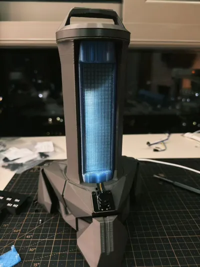
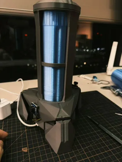
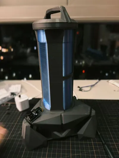
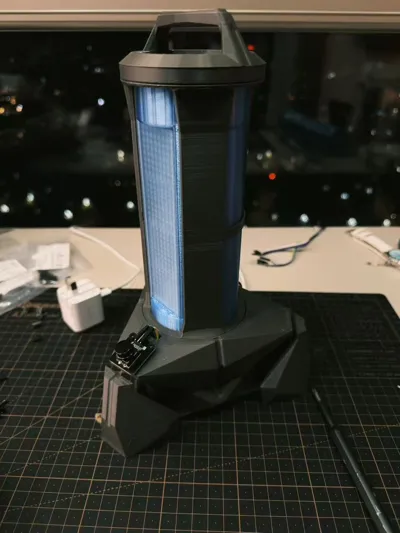
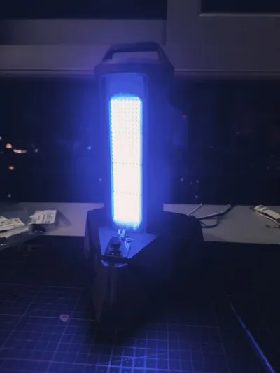
This is a self-made VALORANT Spike-themed electronic clock, purely a personal DIY project. Valorant players and electronics DIY enthusiasts can refer to this for their own builds.
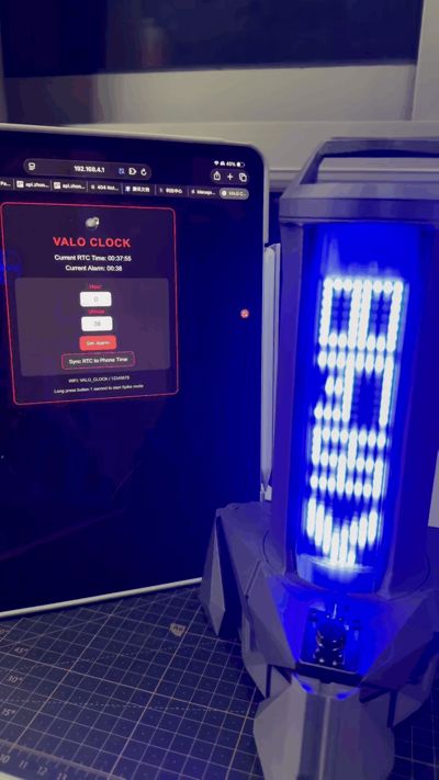
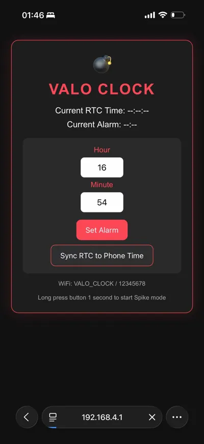
Normally, it displays the time. Four 8x8 MAX7219 dot matrix displays are chained together to show hours, minutes, and seconds. A Valorant logo is placed on the right side of the screen. Upon startup, there's a scrolling animation with a buzzer sound, giving it a nice touch. Long-press the button to directly enter Spike mode. A 3-2-1 countdown animation with progressive sound effects replicates the feeling of defusing the bomb in the game. After the countdown, the dot matrix flashes across the entire screen, and the buzzer rings faster and faster, simulating an explosive countdown. It automatically returns to normal time after 18 seconds; pressing the button mid-countdown can force it to stop. It also has an alarm function; set your own time, and at the set time, it will automatically trigger a sound and light alarm, with the buzzer sounding and the logo flashing, gradually increasing in tempo. Pressing the button once turns it off, making operation simple. Connect your phone to its hotspot for remote control. It automatically activates WiFi upon startup, named VALO_CLOCK with a default password of 12345678. Once connected, open a web browser to 192.168.4.1 to view the time in real-time, set alarms, and sync time with your phone with one click, making time calibration super convenient without needing to fiddle with the board every time. The button logic is also simple: a short press turns off the alarm or stops the Spike mode; a long press for 1 second manually activates Spike mode.
Here are all the components needed to make this; just buy them accordingly:
- 1 NodeMCU ESP8266 development board
- 4 MAX7219 8x8 dot matrix displays (for serial connection)
- 1 DS3231 high-precision clock module (keeps accurate time even when powered off, no need to recalibrate every time it starts up)
- 1 3-pin button module
- 1 active buzzer module
- Several DuPont wires (female-to-female) 10cm and 20cm
- 1 MicroUSB data cable (for flashing / power supply), 1 reputable 5V 2A or higher charging head (for external power supply)
Here are the screws used; just buy them accordingly:
- 6 M3×10 self-tapping screws: used to secure the main casing and dot matrix display modules
- 4 M2.5×6 screws: used to secure internal circuit boards and functional modules
- 2 M3×4 screws: used to secure small components and terminal blocks
Regarding copyright: This is my original DIY project. Everyone is welcome to help optimize and modify the design, but all derivative works must be posted under this original work. Unauthorized reposting or secondary distribution is prohibited. Any form of commercial use is also prohibited; do not use my design for profit.
Finally, a reminder to avoid pitfalls:
- For external power supply, always use a reputable 5V 2A or higher charging head + original data cable. Otherwise, it may suffer from insufficient power, preventing the board from starting and causing the dot matrix to fully light up (plugging it in a few more times should fix it)
- It's recommended to flash the board first before connecting components to test if the functions are successful.
Documentation (3)
License
You may create derivative works based on this object, provided that all such derivative works are published exclusively on the MakerWorld platform and include proper attribution to the original creator. You may not share, upload, host, distribute, or publish this object—or any derivative work of this object—on any other digital platform, marketplace, or distribution channel. Commercial use of this object and any derivative works is strictly prohibited. This includes, but is not limited to, selling, renting, sublicensing, or using the object in any context in which you receive monetary compensation or other financial benefits.
Comment & Rating (0)