
Parametric Dowel Jig with 608ZZ Bearings
Print Profile(4)
Bill of Materials


Description
Description — English
TL;DR
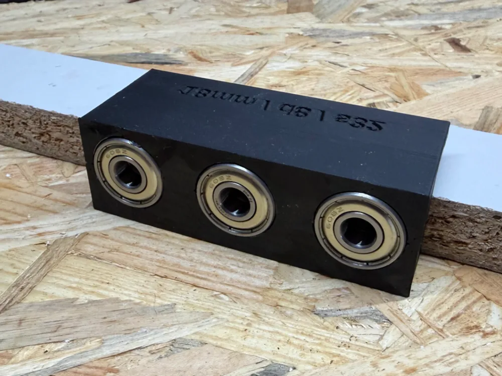
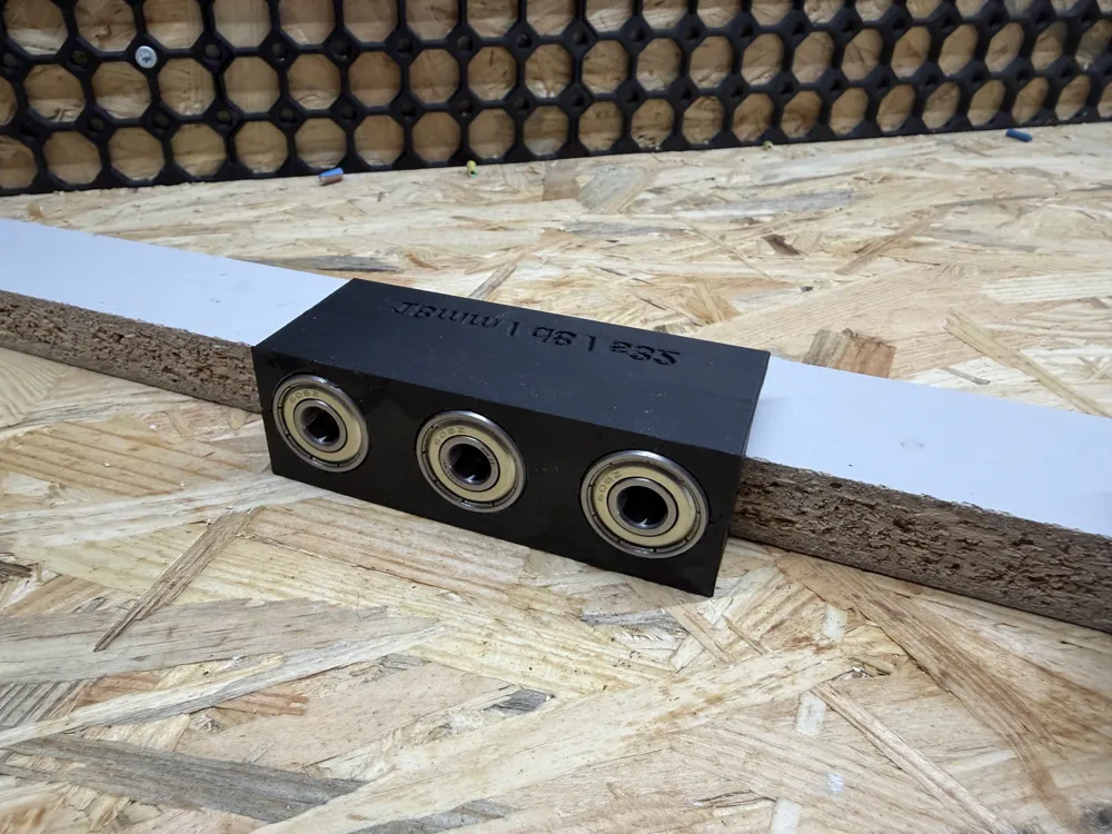
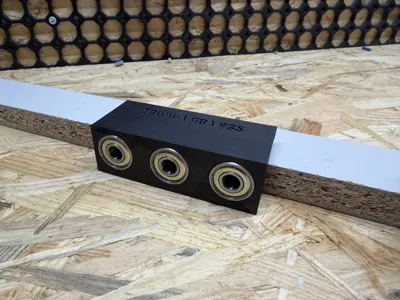
A fully parametric, 3D-printable dowel drilling jig that uses 608ZZ skateboard bearings as drill guides. Edge fence auto-centers holes in 18mm boards. Optional corner end stop lets you reference from the board's edge — print a left + right pair for perfectly matched face and edge drilling on cabinet joints. Supports needed inside bearing pockets (bridge over ~22mm pocket floor).
Full description
What it does
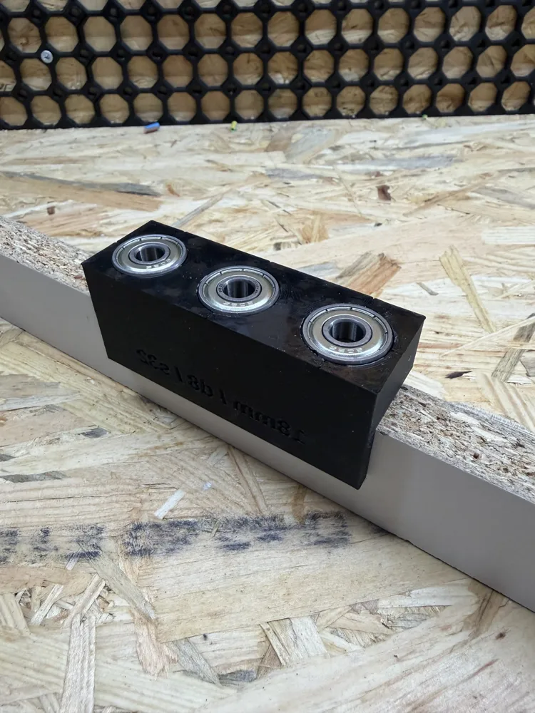
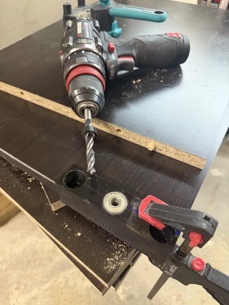
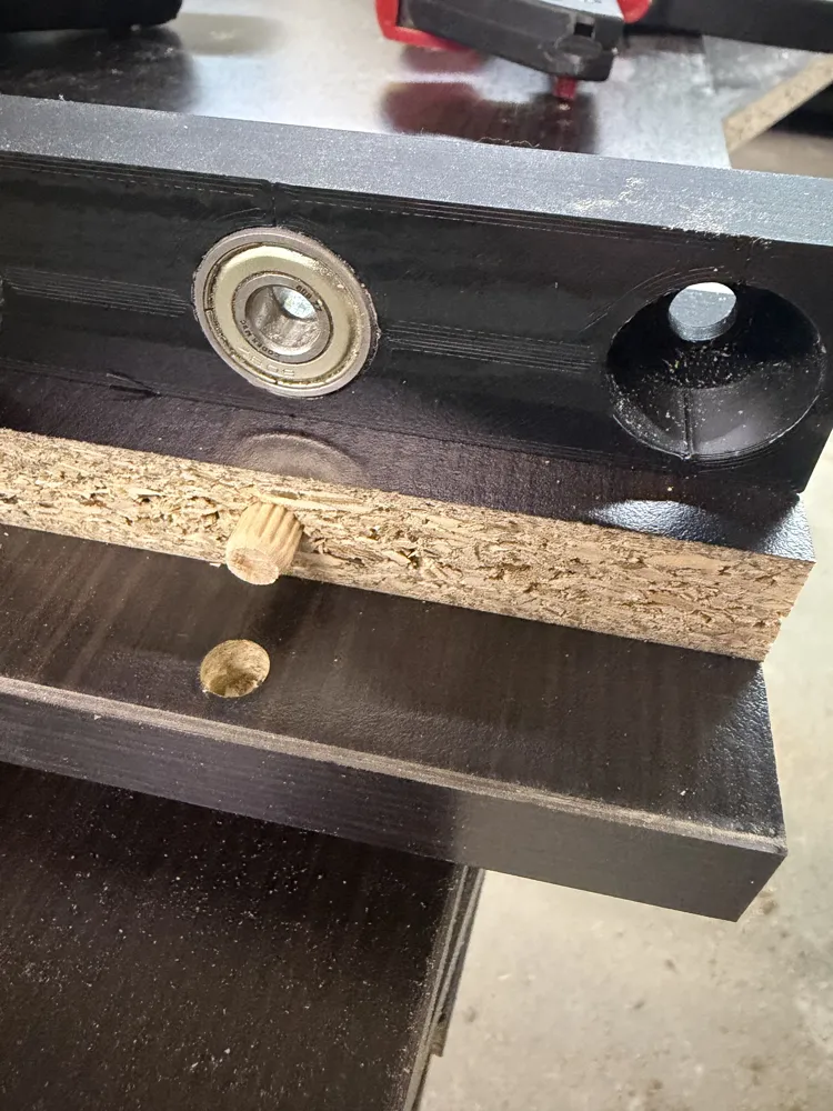
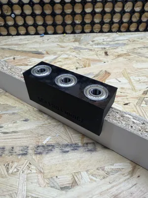
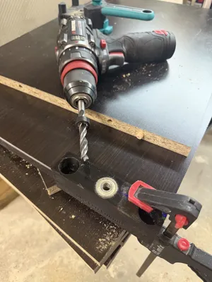
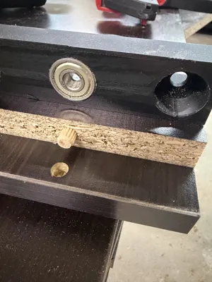
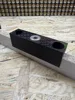
This jig sits on the face of a board with its fence pressed against the edge. The fence automatically positions the drill holes at the center of the board's thickness (9mm on 18mm stock). Two stacked 608ZZ bearings per hole guide the drill bit at a precise 90° angle, eliminating wander and ensuring repeatable, accurate dowel joints.
Default configuration: 3 holes at 32mm spacing (System 32), 8mm drill bit, 18mm board — but every dimension is parametric.
End stop / corner reference
The jig has three end stop modes, selectable in the Customizer:
- none — no end stop. Position the jig freely anywhere along the board, align using the centerline grooves on top. Best for mid-board joints or when you need flexible hole placement.
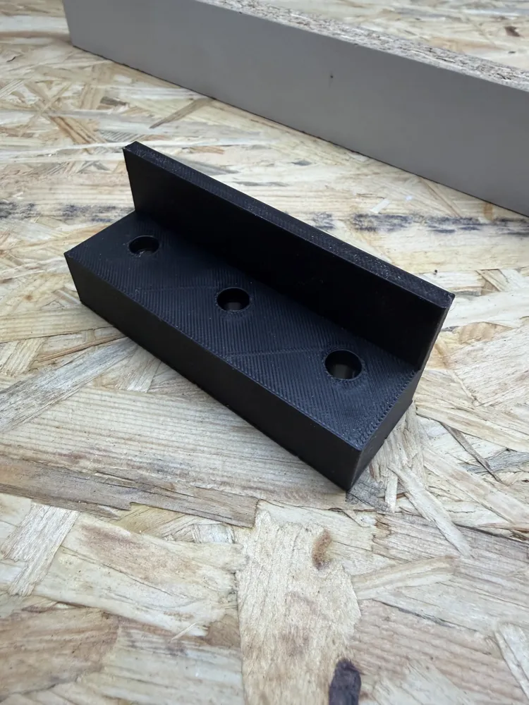
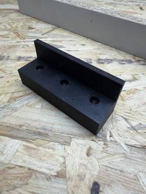
- left — adds a wall on the left side that hooks the end of the board. The stop sits outside the jig body, so side_marginalways equals the distance from the board's end to the first hole center, regardless of stop thickness.
- right — mirror of left.
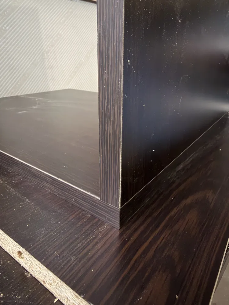
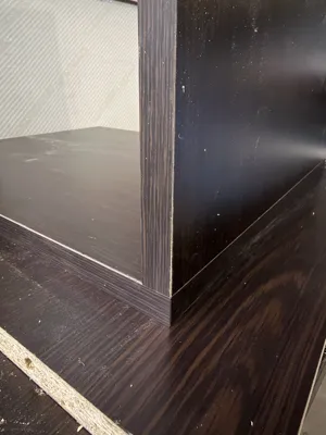
For cabinet assembly, print one left and one right jig. Use one on the panel face (drilling into the face) and the other on the mating panel's edge (drilling into the end grain). Both jigs reference the same corner, so the dowel holes are guaranteed to align — same distance from the edge, same distance from the end.
Key parameters (Customizer)
- Board thickness (default 18mm)
- Bearing tolerance (default 0.05mm per side — tight press fit)
- Drill hole tolerance (default 0.10mm)
- Number of holes (1–6) and spacing (default 32mm)
- Fence depth (default 20mm)
- End stop: none / left / right
- End stop thickness (default 5mm)
- Centerline groove depth and label engraving
Bill of materials
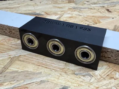
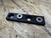
- 2× 608ZZ bearings per hole (6 total for 3-hole jig)
- Standard 8mm brad-point drill bit
Print recommendations
- Material: PETG recommended (better wear resistance than PLA)
- Orientation: default (flip_for_print = true) — bearing pockets face the build plate, fence points up
- Supports needed inside bearing pockets — at the top of each pocket there is a ~22mm bridge (pocket floor with 8mm drill hole). Use snug or tree(auto) supports. Clean out pockets after printing.
- Recommended: 3 wall loops, 4+ top/bottom layers for rigidity around bearing pockets
- Print a single-hole test piece first to verify bearing fit on your printer
Bearing installation
Press bearings into pockets using a vise or clamp — they should be a tight friction fit. If too loose, reduce bearing_tol; if too tight, increase it. Start with 0.05mm and adjust in 0.05mm increments. Or just print the bearing test model.
Description — Polish
TL;DR
W pełni parametryczny wzornik do wiercenia otworów pod kołki 8mm, z łożyskami 608ZZ jako prowadnicami wiertła. Ogranicznik krawędziowy (fence) automatycznie centruje otwory na grubość płyty 18mm. Opcjonalny ogranicznik narożny (end stop) pozwala referencyjnie wiercić od rogu formatki — wydrukuj parę lewy + prawy, żeby idealnie trafić kołki wiercąc raz w czole wieńca, a raz w boku szafki. Supporty potrzebne wewnątrz kieszeni łożyskowych (bridge ~22mm).
Pełny opis
Do czego służy
Wzornik kładzie się na czole (płaszczyźnie) formatki, z ogranicznikiem krawędziowym (fence) opartym o krawędź. Fence automatycznie ustawia oś otworów na środek grubości płyty (9mm przy płycie 18mm). Dwa łożyska 608ZZ ułożone w stos na każdy otwór prowadzą wiertło pod kątem 90°, eliminując dryf i zapewniając powtarzalne, precyzyjne połączenia kołkowe.
Domyślna konfiguracja: 3 otwory w rozstawie 32mm (System 32), wiertło 8mm, płyta 18mm — ale każdy wymiar jest parametryczny.
Ogranicznik narożny (end stop)
Wzornik ma trzy tryby ogranicznika, wybierane w Customizerze:
- none (brak) — brak ogranicznika narożnego. Wzornik pozycjonujesz swobodnie w dowolnym miejscu formatki, wyrównując się po liniach centrujących na górze. Najlepszy do połączeń w środku formatki lub gdy potrzebujesz elastycznego pozycjonowania otworów.
- left (lewy) — dodaje ściankę po lewej stronie, która opiera się o koniec formatki. Ogranicznik jest na zewnątrzkorpusu wzornika, więc side_margin zawsze = odległość od końca formatki do środka pierwszego otworu, niezależnie od grubości ogranicznika.
- right (prawy) — lustrzane odbicie lewego.
Do montażu szafek wydrukuj jeden lewy i jeden prawy wzornik. Jednym wiercisz w czole wieńca (otwory w płaszczyznę), drugim w boku szafki (otwory w czoło). Oba referencyjnie odliczają od tego samego rogu, więc kołki gwarantowanie się zgadzają — ta sama odległość od krawędzi, ta sama odległość od końca formatki.
Kluczowe parametry (Customizer)
- Grubość płyty (domyślnie 18mm)
- Tolerancja kieszeni na łożysko (domyślnie 0.05mm na stronę — ciasny wcisk)
- Tolerancja otworu przelotowego na wiertło (domyślnie 0.10mm)
- Liczba otworów (1–6) i rozstaw (domyślnie 32mm)
- Głębokość ogranicznika krawędziowego (fence, domyślnie 20mm)
- Ogranicznik narożny: brak / lewy / prawy
- Grubość ogranicznika narożnego (domyślnie 5mm)
- Głębokość rowków centrujących i grawerowania etykiety
Lista materiałów
- 2× łożyska 608ZZ na otwór (6 sztuk dla wersji 3-otworowej)
- Wiertło kręte 8mm (najlepiej z ostrzem centrującym)
Zalecenia druku
- Materiał: PETG zalecany (lepsza odporność na ścieranie niż PLA)
- Orientacja: domyślna (flip_for_print = true) — kieszenie na łożyska leżą na stole, fence i end stop do góry
- Supporty potrzebne wewnątrz kieszeni łożyskowych — na szczycie każdej kieszeni jest bridge ~22mm (podłoga kieszeni z otworem 8mm). Użyj supportów snug lub tree(auto). Po wydruku wyczyść kieszenie z resztek supportu.
- Zalecane: 3 wall loops, 4+ warstw top/bottom dla sztywności wokół kieszeni na łożyska
- Wydrukuj najpierw wersję testową z jednym otworem, żeby sprawdzić pasowanie łożyska na swojej drukarce
Montaż łożysk
Łożyska wciskaj w kieszenie za pomocą imadła lub zacisku — powinny trzymać na ciasny wcisk tarciowy. Jeśli za luźno, zmniejsz bearing_tol; jeśli za ciasno, zwiększ. Zacznij od 0.05mm i koryguj co 0.05mm. Albo wydrukuj wzornik dopasowania łożysk.
License

You shall not share, sub-license, sell, rent, host, transfer, or distribute in any way the digital or 3D printed versions of this object, nor any other derivative work of this object in its digital or physical format (including - but not limited to - remixes of this object, and hosting on other digital platforms). The objects may not be used without permission in any way whatsoever in which you charge money, or collect fees.


Comment & Rating (8)