Snapmaker U1 3DEE Top Cover


Print Profile(0)
Description
Snapmaker U1 3DEE Top Cover
6/17/26 - UPDATE: V2.0
Thank you, and with community feedback, I was able to fix pieces 1 and 4 to allow a proper bridge for the groove in the glass. Before, there was not enough overhang and the piece will not bridge properly.
The fix was to add 1mm extension to allow tree supports to extend to the bridge.
Thank you again for the feedback, it allows me to create a better print.
-------------------------------------------------------------------------------------------------------------------------------
Hello all,
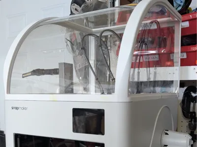
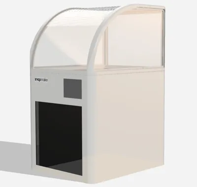
Ever since preordering the printer, I have been looking for a somewhat minimal and un-obtrusive design. The ikea cover comes in very close but did not like how it looked. I started learning and designing in fusion and eventually came up with this design. It took me a bit to learn and create, so I hope you makers alike enjoy it.
I want to start off by saying I did not design this cover for anything other than PLA and PETG. It was not designed to keep/retain heat for higher temp materials so please keep that in mind. I wanted it simply to cover the top of the printer when not in use to stop dust and debris from accumulating. Thus, the minimal and thin plastic sheet design.
--------------------------------------------------------------------------------------------------------------------------------
Materials needed:
x3 - 24x36" clear PET/Plexiglass Sheets. 1mm or 0.04" by Langaelex Store (I ended up buying the 6pack for myself)
https://www.amazon.com/dp/B0CR47W6WC?th=1
x1 - Solvent adhesive (or similar)
https://www.amazon.com/dp/B0DS69HMN6?ref=ppx_yo2ov_dt_b_fed_asin_title
or Weld On 16 (thicker viscosity)
--------------------------------------------------------------------------------------------------------------------------------
This was designed to print on a snapmaker u1. Atleast 270x270x270 build plate.
If you are using the STL, please make sure to split to objects once loaded an you can move them around. If you have faith in your printer, this can easily by a 3 plate print.
I recommend printing the first plate “by object” with a slower speed as they have very small footprints and may come off. I did not require use of a brim or anything, but please use your own judgment. All other plates should be printed normally by layer. I also recommend using a solvent based adhesive. Plate 4 may require support for the large fillet if you are having trouble printing it with insufficient cooling.
Some recommended settings if you are using the STL and not importing 3mf. If not stated, using default settings.
Filament: PETG
Wall loops: 4
Top/Bottom layers: 5
Bridging: flow ratio - 1.5
internal flow ratio - 1.5
external/internal bridge density - 100%
speed external - 15
speed internal - 45
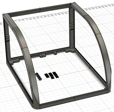
Below and in the included 3mf file is how I printed it. Each part is labeled according to # to help in assembly provided in last picture below. There are four of the 3mm thick connectors (shown in plate 1). The rest are 4mm thick used almost everywhere. The 3mm is only used on the front connector to join pieces #7 to #8. However, depending on how well your printer is tuned, you may need it for other locations. Please print extra according to your needs.

-------------------------------------------------------------------------------------------------------------------------------------
Preparations
You will need two cutouts from your clear PET sheet in the following dimensions for the front and back sheet. Please make sure you trim and test fit when you are at that step. You can measure 1-2mm shorter if you'd like a looser fit; but I don't recommend any longer.
Back panel - 380mm x 275mm
Front panel - 380mm x 648mm
-----------------
Please take note of the fillets in the connectors. It helps align and snap the connectors in. These connectors was inspired by a youtuber who was designing something for his shelf. I apologize I cannot recall or find the video of this youtuber (please let me know if you recognize it). These connectors are designed so that you can easily pull it apart and test fit/install the clear plastic panels only. The final process should involve gluing the parts together. Again, I do recommend a solvent adhesive.


-------------------------------------------------------------------------------------------------------------------------------
Step 1
Connect one of the back corner pieces as shown. In this case, I will be referencing the back right corner. Use 4mm connector.
Lay it flat on the table once assembled.

Step 2
Connect the front right corner pieces as shown. Use 4mm connector.

Step 3
Connect your two pieces together and lay it on top of your clear PET Sheet. I am referencing an actual picture from a previous design so it may look slightly different. Please follow the instructions and you should be fine.
Your longest edge should be about 480mm or 18.9in.


Step 4
Lastly, we need to assemble the top piece that will hold the rear/front clear PET Sheet.
Use one 4mm connector.

Step 5
Repeat steps 1-3 for the other side. At this point, you should be able to test fit your rear and front clear PET Sheets. Ensure the lengths fill in the grooves. Trim and test fit as necessary.

Step 6
Join the two pieces together WITH your two clear PET Sheets. The connectors along with the clear sheets should give you enough rigidity to test fit on top of your printer at this point. If all goes well…
Please, please, please glue all pieces together.

Thank you!
Please let me know if you have any questions or if anything i unclear.
I would love to see pictures if all works out well.
Boost Me (for free)
Thank you so much
Comment & Rating (7)