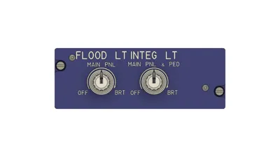
Airbus A320 Lightning Panel


Print Profile(2)
Description
Introduction
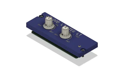
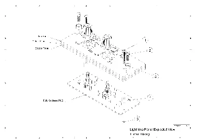
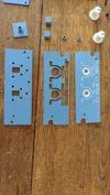
This is my first proper panel with a custom PCB and is how I plan on making them in the future. The panel is a 1:1 scale as the real life panel designed with 10mm clearence on either edges to mount on to the pedestal. The panel consists of three separate panels that are mounted together with two M3 screws. The PCB also gets mounted on the same screws from underneath and has a 5 pin JST-XH connector to wire to an external microcontroller for simplicity. In the future when I make my other panels I will include a port to connect this panel to, so stay tuned!
Parts needed
PCB:
11x 3mm flat top warm white LEDs - https://www.aliexpress.com/item/32281183062.html
2x vertical mounted 10K RK097 potentiometers - https://www.aliexpress.com/item/1005009717287004.html
1x standard 1K resistor
1x Bourns 3296W potentiometer trimmer or similar, 50K - https://www.aliexpress.com/item/1005002633262032.html
1x 5 pin JST-XH connector, I recommend buying a set of different pins - https://www.aliexpress.com/item/1005010615522731.html
CN5711 LED chip (see below)
Panels:
2x M3x25mm round hex head screws - https://www.aliexpress.com/item/1005008358579825.html
2x M4x12mm screws for mounting to pedestal - https://www.aliexpress.com/item/4000881788038.html
M3 nuts
Printing process and settings
If there is a .3mf file it should have everything loaded in the correct way and with the correct settings. But you can double check all the settings anyway:
NOTE: Make sure in the filaments tab that the transparent filament is the first color or else the infill will merge in your object. Remove and add the blue filament if it still doesn't work. There are two print profiles, 0.2mm and 0.4mm nozzle. The top panel isprinted with 0.2 for better quality on text.
I use three different PLA filaments to acheive the top panels with the text and LED backligtning. Blue, I use Panchromas Muted Blue PLA filament. White, I use a standard white filament, nothing to specific. Transparent, I use FormFuturas "easy fil PLA natural" but any transparent filament works. The more see throught the more light will shine through.
The transparent filament makes the "blocks" with text on top which sit inside of the top panel to spread/diffuse the light to a larger area. The last layers on top is a seperate 0.3mm (3 layer) thick object which should be printed in the white filament so that you don't see the infill or previous layers through the text and it makes it look overall better.
When importing do not scale to millimeters and load as a single object with multiple parts. Top Panel objects should be printed in blue, transparent in transparent and the rest of the bodies in white.
Ironing Type - Topmost surface only on the top panel
Infill type - Rectilinear
Infill density - 100% for 0.2 nozzle (10% for transparent bodies), 45% for standard panels and 100% for knobs and handles
Layer height - 0.1 for top panels and knobs/handles and 0.15 for other panels.
Make sure the ironing pattern goes from left to right of the panel, side to side. Orient it in the correct way and make sure all panels are oriented the same way. If you use OrcaSlicer or similar you can change the ironing angle.
Use these amazing knobs by MANTOGA: https://www.printables.com/model/441922-airbus-a320-lighting-knob-v2
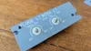
PCB and ordering
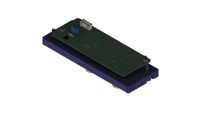
The PCB has five pinouts, GND, 5V, two Analogs for the pots and one PWM that drives the LED chip. The LED chip is a CN5711 chip uses a standard PWM signal to regulate the voltage and drive the LEDs. On the back side it's connected to a thermal heatsink with some via holes. The analog pins connect to a standard arduino analog pin and reads the signal. In the future when I design my other panels I will intentionally put a JST connector that connects to a microcontroller for less wires and USBs but for now you can use a small mc like arduino pro micro.
I ordered my PCB from JLCPCB with the special PCB-assembly option for the CN5711 chip since it's surface mounted and I highly recommend you do the same. They require two extra files, a bom and CPL (placements) file which are also availible. All other parts i soldered myself.
Assembly
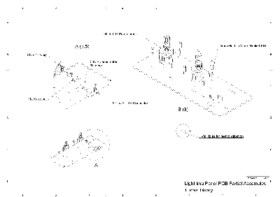
Start by assembling the PCB and the LEDs. Put an LED in a slot/pin and put the solder guide on top. Flip it over and use the extra blocks to hold up the board at the same height. Reapeat for the rest of the LEDs. Then solder on the potentiometers (ensure they are mounted straight vertical) and move to the back side. Solder the 1K resistor and pot trim and lastly the JST-XH connector in the shown orientation.
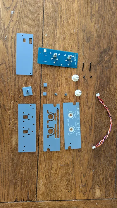
Next, assemble the whole panel. Stack the 3 panels on top of each other and insert the M3 screws [1]. Put on the PCB spacers [4] and next the PCB ensuring everything fits. Then just use two M3 nuts [5] to secure it in place. Additionaly you can print the back cover to protect some of the electronics, in that case just use two additional nuts to mount it on the back. Finally, use two M4 screws and my other model for the screw caps [2 & 3] to mount to rails beneath the panel.
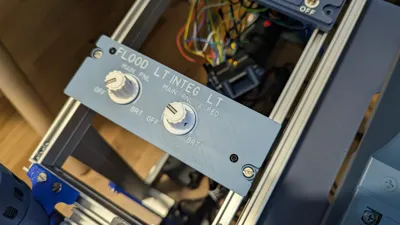
And the panel is done! I use the mobiflight software to control everything and use it with my simulator which is quite intuitive and many tutorials exist on the internet.
Be sure to check out my other models such as the screw caps for the mounting screws and the pedestal frame! ;)
Comment & Rating (2)