Button Box for Simulators


Print Profile(1)
Bill of Materials
- On-Off-On Latching Switches x 6: https://de.aliexpress.com/item/1005008390806669.html
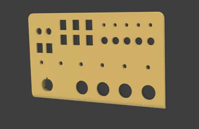
- Arcade buttons (24mm, if you want to use 30mm you'd have to change the 3D model) x 4: https://de.aliexpress.com/item/4001316815891.html
- Ignition key x 1: https://de.aliexpress.com/item/1005009015179868.html
- Dupont Wires (Female end for BBI-64, other side cut, remove insulation and solder) x 120: https://de.aliexpress.com/item/1005003641187997.html
- USB-Passthrough (USB-3.0 to USB-3.0 for BBI-64) x 1: https://de.aliexpress.com/item/1005007721928643.html
- On-Off-On Latching Levers x 5: https://de.aliexpress.com/item/1005008284356899.html
- Togge-Switch with red Cap x 2: https://de.aliexpress.com/item/1005010407544218.html
- Momentary Buttons x 5: https://de.aliexpress.com/item/1005003302861259.html
- Rotary Encoders with Push-Button x 6: https://de.aliexpress.com/item/1005009780872386.html
Description
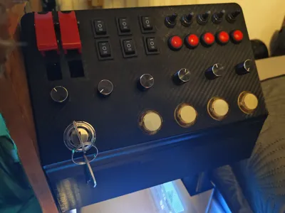
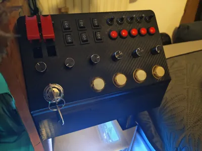
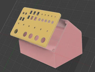
This is my Button Box for simulations, made with AliExpress-Electronics and an BBI-64 from Leo Bodnar made in Fusion 360, printed on P1S.
I'll try to find all the links to my used buttons, switches and ignition key so that you can use the same ones. Wiring them up using the Leo Bodnar-Board requires some soldering, but it's an awesome project to do over a few days.
I personally used PETG for this project, using a Carbon textured print plate for the Lid, adds a nice look without having to use some sort of carbon-vinyl.
Other filament types should be fine too.
To wire up the buttons:
You can easily connect all the grounds and then just plug them into one of the BBI-64 ground pins, I personally went with one ground per Button-Style (so all together 7 grounds)
Then just connect each “output” of the switch with one spot on the BBI-64.
!Make sure to wire the Rotary encoders according to the BBI-64 configuration, making sure that the output for ex. rotary encoder 1 is on pin 0 for turning it left and pin 1 for turning it right. The button function can then be plugged into free spots not used by the rotary function.!
If wanted and asked for I can try and create a wiring diagram for my used layout.
You will have to change the model if using other buttons and especially a different ignition switch, as my Lid is especially made for the ignition key linked in the part-list and shown in this Picture:

It has a very specific taper beneath the threaded part (also the flat spot on the threads is modeled) and three legs, one is round and two have a very specific shape as seen in my copied 3D-model)

Everything else should be self-explanatory, but if you have questions I'm open for them.
License
You may create derivative works based on this object, provided that all such derivative works are published exclusively on the MakerWorld platform and include proper attribution to the original creator. You may not share, upload, host, distribute, or publish this object—or any derivative work of this object—on any other digital platform, marketplace, or distribution channel. Commercial use of this object and any derivative works is strictly prohibited. This includes, but is not limited to, selling, renting, sublicensing, or using the object in any context in which you receive monetary compensation or other financial benefits.
Comment & Rating (0)