
OneClick | Customisable MacroPad | No AMS
Print Profile(1)
Bill of Materials


Description
Hello there !
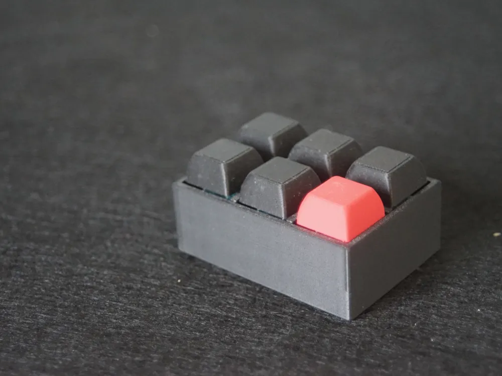
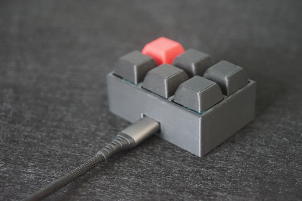
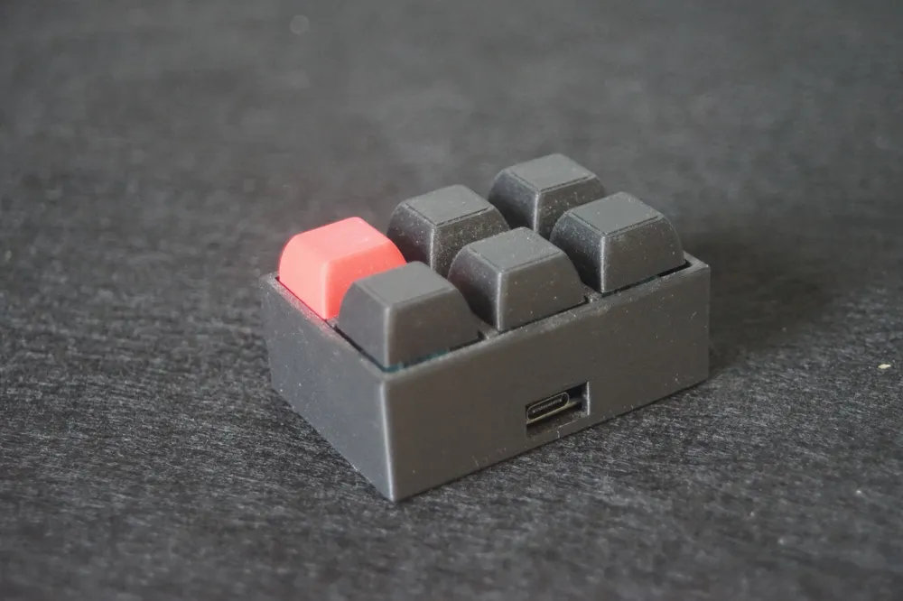
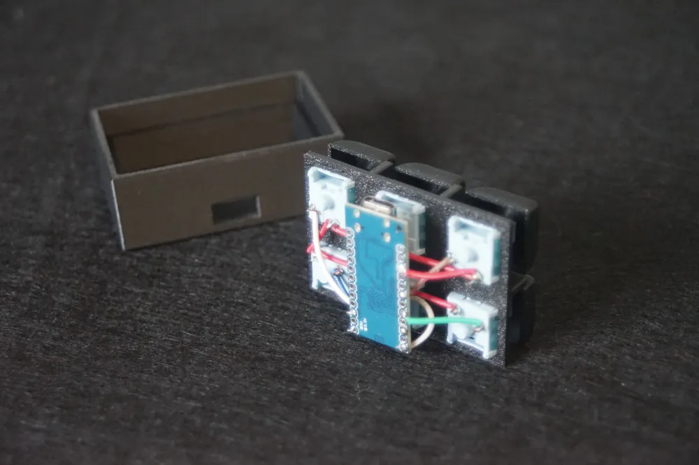
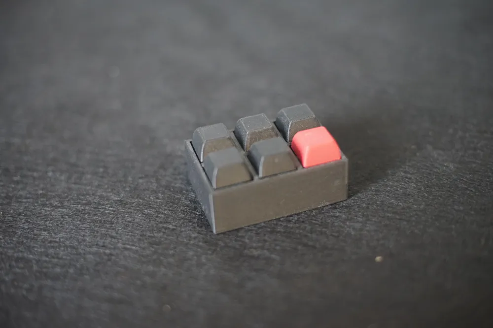
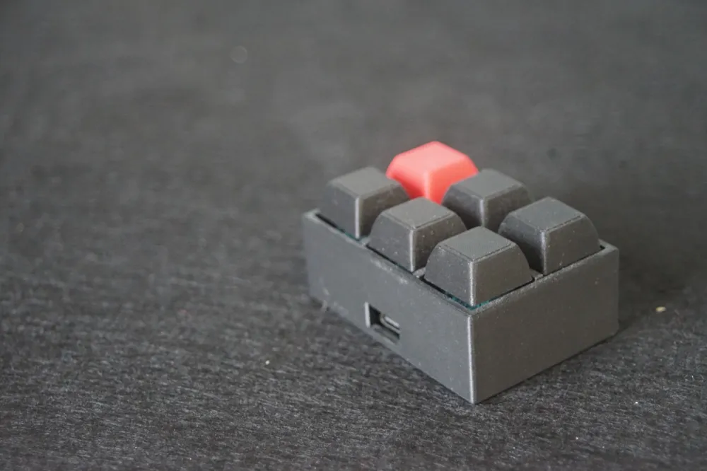
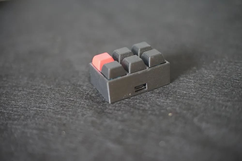
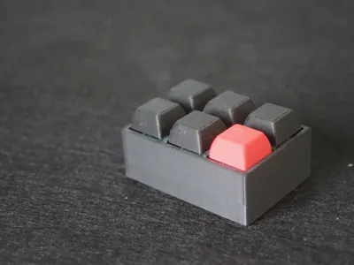
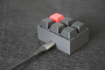
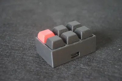
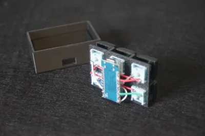
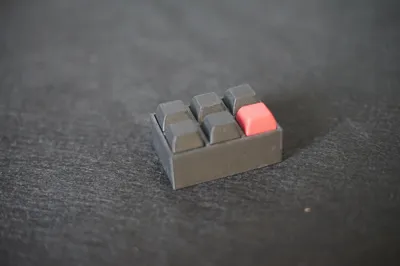
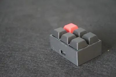
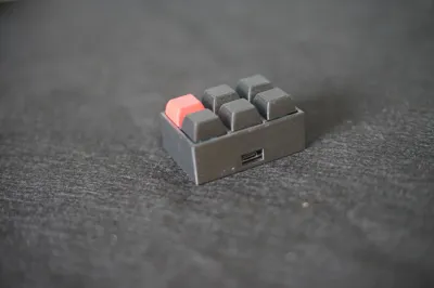
Here's OneClick, my first take on a completely customisable macropad. Access any app, control your music or open your terminal in just one click. This six-button macropad is an easy-to-print and assemble model. Connect it to your computer, upload the code, change a few settings and have fun !
Printable on all BambuLab printers using only 1 plate (if monochrome or with ams) and sliced with care for a good looking print.
List of materials:
- PLA Basic (probably works with other materials, but I haven't tested that)
- Arduino ProMicro, you can find one here
- Small cables, you can find a roll here
- 6 MX-Switches, I recommend tactile switches for a more pleasant feeling, but it's of course up to you. You can find some here.
- 1 USB-C cable to connect to your computer
List of tools:
- Soldering iron
- Something to cut cables
Building instructions:
I recommend using different colors of cables for easier comprehension during the building process. In any case, you will not see them, except of course if your case is transparent.
Step 1:
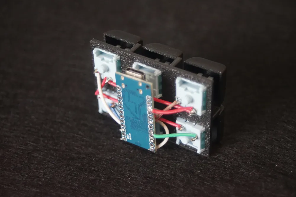
Place all 6 switches in the holes of the plate. Make sure that the metal pins are facing inwards.
Step 2:
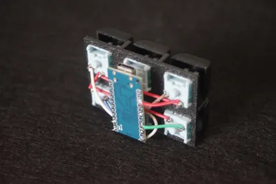
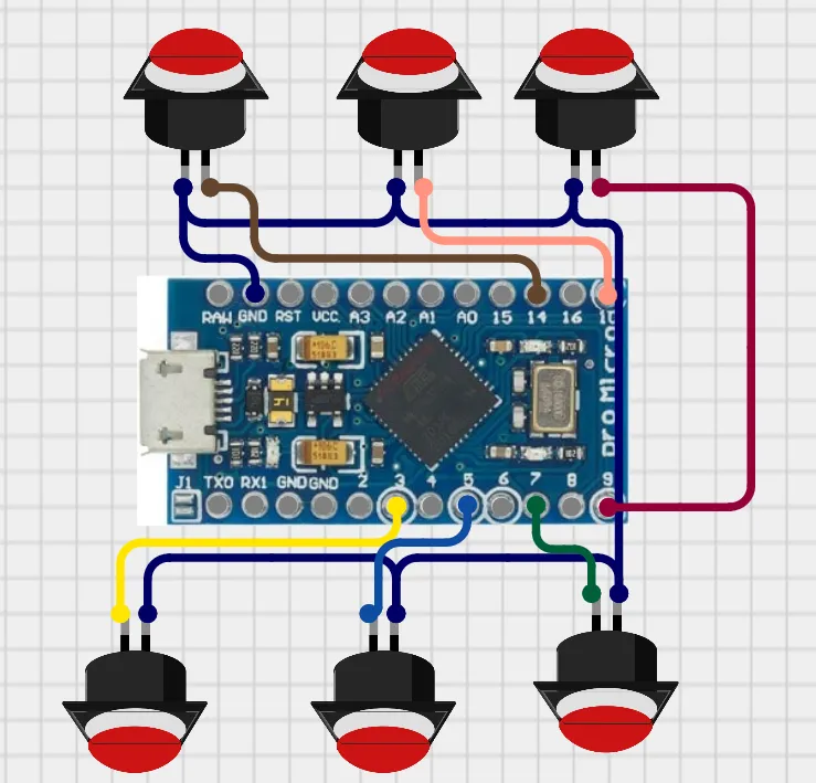
Solder 1 metal pin of each switch together (purple cable on image) leaving as less floating cable as possible. This will be the ground (to give power to the switches).
Step 2-b:
Take a cable and connect 1 side to one of the metal pins with the ground already coneected. I recommend connecting one of the corner switches (like on the image, top left switch).
Step 3:
Take 6 (different colors if possible) cables and solder each one on the free metal pin of each switch.
Step 4:
Verify what cable will go on to what hole on the Arduino. I recommend using the holes I show on the image because they don't touch each other, but you can choose. If you change the holes, you will have to change the beginning of the code.
Step 4-b:
Cut the cables to the right length, not too long so they push the pcb away but not too short so it won't fit.
Step 5:
Solder the cables to the holes in the Arduino. I recommend that the components on the pcb do not face towards the switches (unlike my version). It is going to be easier to see the numbers and text.
Step 6:
Place the assembly into the case, pop on the keycaps.
Step 7:
Install Arduino IDE (guide here) and the necessary drivers for the board (for Windows or Mac/Linux). Plug the board in, choose the right port and board in the sofware and copy paste the code in the txt file below. Modify it if needed. The current code simulates a press on the F_Keys so be sure to bind them properly.
For a complete guide to add custom shortucs watch this video: Windows Mac Linux(Ubuntu)
Boost Me (for free)
This is my first complex model including electronics so I hope this guide was clear. If you have any questions, don't hesitate to ask in the comment section, I will try to respond in the shortest time possible. Or if you have a recommendation, I will gladly take that too.
A boost would be greatly appreciated!
Enjoy !
Documentation (1)
License

You shall not share, sub-license, sell, rent, host, transfer, or distribute in any way the digital or 3D printed versions of this object, nor any other derivative work of this object in its digital or physical format (including - but not limited to - remixes of this object, and hosting on other digital platforms). The objects may not be used without permission in any way whatsoever in which you charge money, or collect fees.


Comment & Rating (2)