Ultimate DIY Busbar System (100mm²)


Print Profile(1)
Description
Ultimate DIY Busbar System (100mm²) | High-Current Power Distro
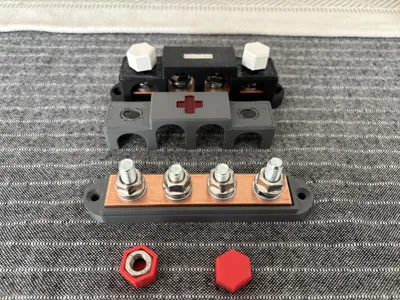
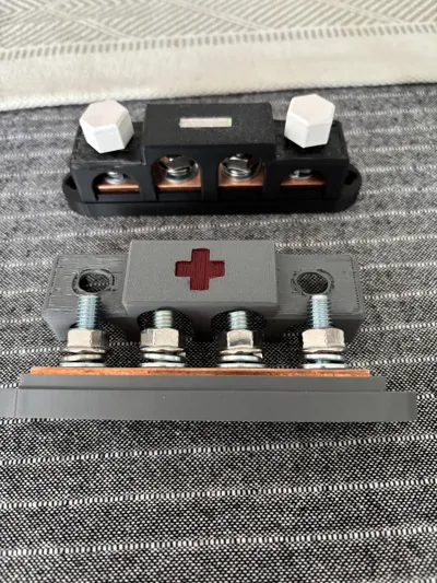
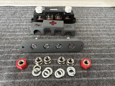
This is a professional-grade, 5-part modular busbar system designed for extreme DIY electrical builds (RV, Solar, Marine). It uses a massive 100mm² copper core (20x5mm) and includes specialized tools for perfect assembly.
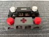
What's in the Box? (5 STL Files)
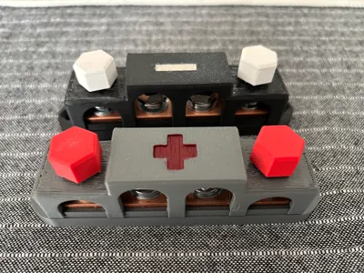
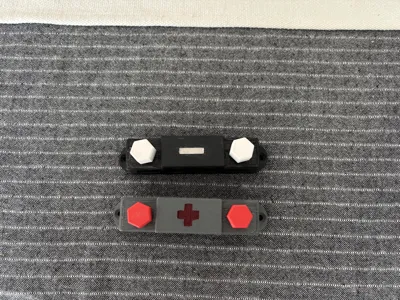
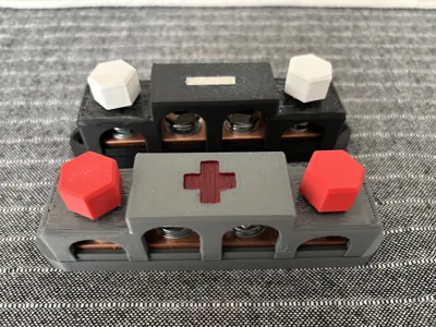
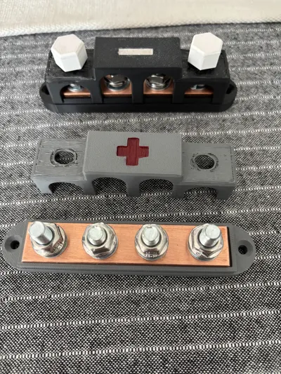
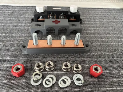
- Busbar Body: Main structural base designed for 4 bolts: 2x M8x30 and 2x M8x25.
- Top Cover (+): Safety lid with embossed "PLUS" marking for easy identification.
- Top Cover (-): Safety lid with embossed "MINUS" marking.
- Bolt Cap: Inserts to seat and secure the screws connecting the Top to the Body.
- HoleAligner (Tool): A precision drilling jig. Use this to mark and drill perfectly centered holes in your 20x5mm copper bar. No more misaligned bolts!
Hardware Requirements
To assemble this beast, you will need:
- Copper Bar: 100mm x 20mm x 5mm (M1E Z4 / Cu-ETP).
- Main Bolts: 2x M8x30mm and 2x M8x25mm (Stainless Steel recommended).
- Assembly: 4x M8 Washers and Spring Washers for vibration resistance (crucial for vans!).
Technical Performance (12V/24V/48V DC)
- Rated Current: 250A (Continuous).
- Maximum Load: 320A (Max continuous with ASA/PC housing).
- Surge Capacity: 500A (Short bursts).
- Resistance: Ultra-low voltage drop due to $100mm^2$ cross-section.
Recommended Print Settings
- Material: ASA is mandatory (UV and High-Temp resistant). Avoid PLA/PETG for high-current applications.
- Walls: 4+ loops for structural strength.
- Infill: 40% (Gyroid) or higher.
- Support: Minimal supports may be needed for the Bolt Cap depending on your printer's bridging performance.
Assembly Tips
- Use the HoleAligner to mark the copper bar. Use a center punch before drilling.
- Start with a 3mm pilot hole, then finish with an 8.5mm or 9mm drill bit for the copper.
- Deburr the holes in the copper to ensure a flat, low-resistance connection with the lugs.
- Torque the M8 bolts to 8-10 Nm.
Safety Disclaimer
Designed for high-current systems. Always use a main fuse. Build and use at your own risk.
License
You shall not share, sub-license, sell, rent, host, transfer, or distribute in any way the digital or 3D printed versions of this object, nor any other derivative work of this object in its digital or physical format (including - but not limited to - remixes of this object, and hosting on other digital platforms). The objects may not be used without permission in any way whatsoever in which you charge money, or collect fees.
Comment & Rating (0)