
1-in-4-out Fiber Optic Desktop Terminal Box (Supports Drop Cable Cold Splice/SC/LC Flange)
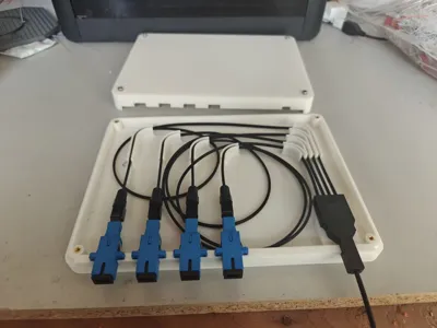
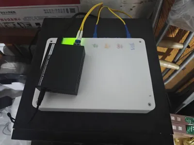
Print Profile(1)
Bill of Materials


- SC/LC 通用法兰接头 x 4:
- 1 分 4 光纤分支器 x 1:
- 空皮线 x 4:
Description
Introduction
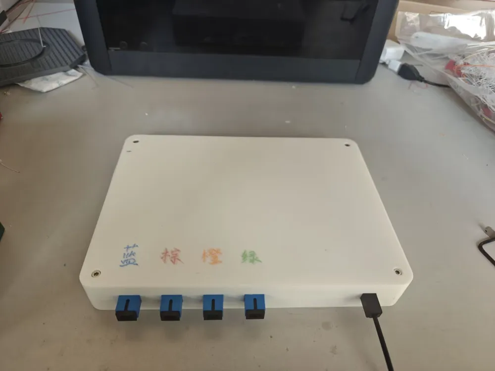
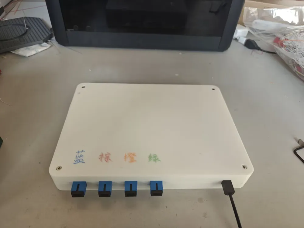
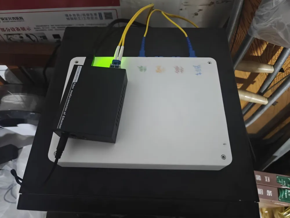
This is a fiber terminal box (Fiber Terminal Box / Patch Panel) designed for Homelab enthusiasts and network engineers
If you are trying to use drop cable (butterfly fiber optic cable) to connect your study switch with your server room's 10 Gigabit (10G) or even 40G/100G (QSFP+ Breakout) connection, this box will provide you with an elegant physical termination and conversion solution. It not only solves the cable management challenge after fiber-to-the-home, but also ensures through structural design extremely low optical loss performance
🛠️ Technical Specifications
- Topology: 1-input 4-output (supports a single multi-core drop cable or multiple drop cables entering in parallel, providing 4 output ports)
- Compatible Cables: Standard 2-core steel wire butterfly fiber optic cable (Drop Cable 2x3mm)
- Fiber Compatibility: Perfectly supports G.657.A1 / A2 bend-insensitive single-mode fiber
- Physical Design:
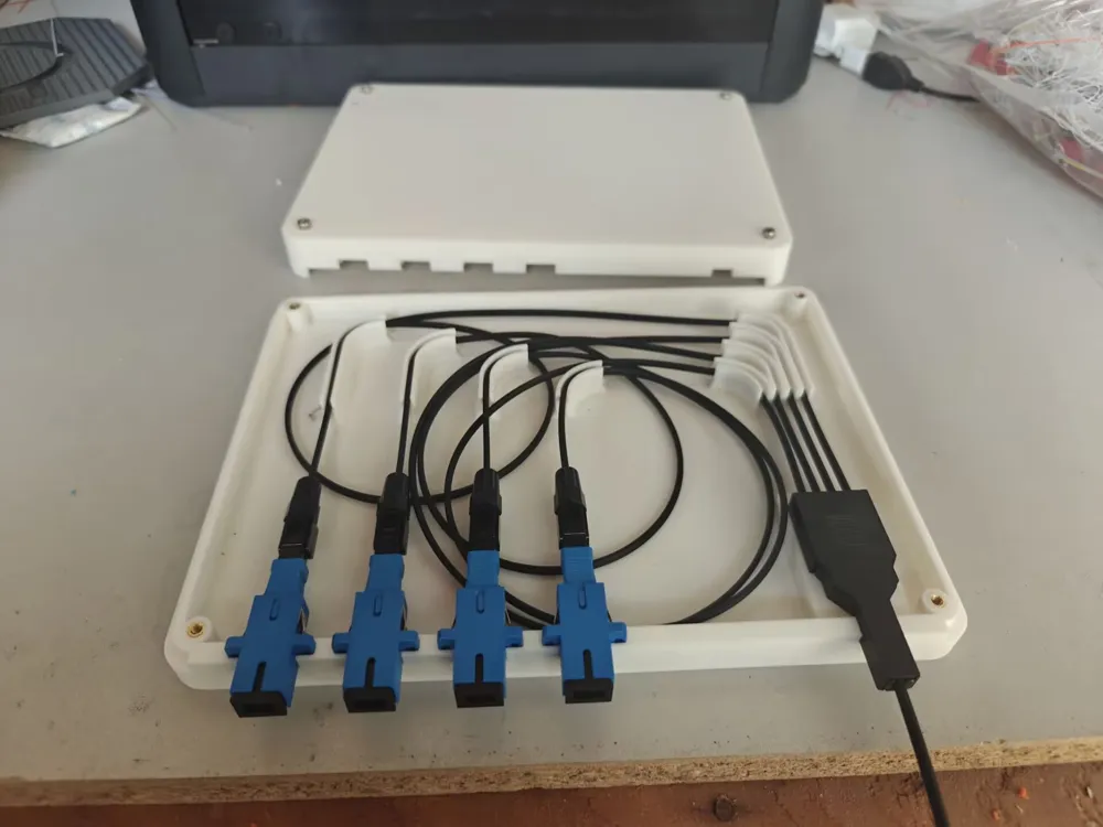
- Bend Radius: The internal cable management structure is designed based on R15mm, far exceeding the minimum physical limit of G.657.A1 (13mm), fundamentally preventing macro-bend loss
- Cable Fixing Structure: Equipped with dedicated drop cable steel wire fixing slots, to prevent cold connectors from detaching or core breakage due to external pulling forces
- Interface Support:
- Internal: Compatible with SC/LC mechanical connectors, quick connectors, or pre-polished pigtails
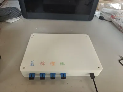
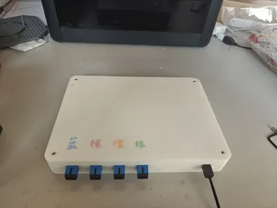
- External: Accommodates 4 standard SC simplex flanges or LC duplex flanges (mounting holes are universal specification)
- Flexible Configuration: Allows mixed installation of single-mode/multi-mode adapters as needed, supporting 40G QSFP+ to 4x10G SFP+ physical layer breakouts
📊 Performance Test Results
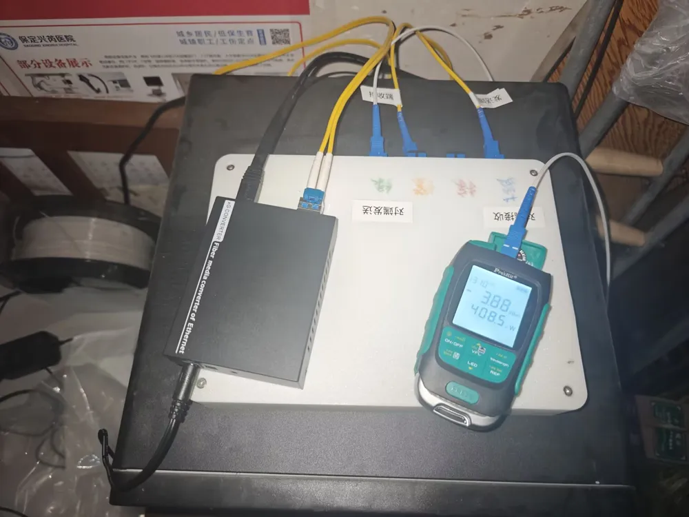
- Test Environment: G.657.A1 drop cable + SC mechanical connector + standard SC adapter
- Test Data:
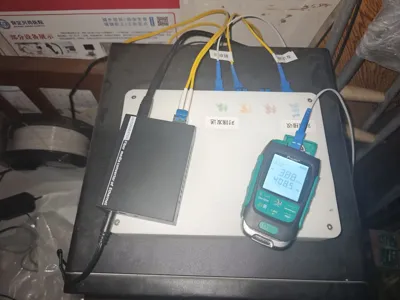
- Received Optical Power: Measured stable between -2.80 ~ -4 dBm, see the actual measurement screenshot in the accompanying image (based on a standard 10km SFP+ LR module)
- Conclusion: Actual tests prove that this design can ensure an extremely high power margin, even at 10G/25G or higher frequencies, it can still ensure physical layer zero packet loss, meeting the stringent requirements of hardcore internal networks
⚠️ Troubleshooting Guide
If your test results drop below -15dBm, don't be quick to doubt my model. Please first check if your fiber end face has cat hair stuck to it, or if your mechanical connector cleaver needs to be replaced
🖨️ Printing Recommendations
- Material: Strongly recommended to use PETG or ABS (server room internal ambient temperature is higher, PLA is prone to creep deformation under long-term stress)
- Layer height: 0.2mm
- Infill: 15% walls recommended 2+ layers, to enhance the strength of the flange snap-in
- Supports: Recommended to enable tree supports to achieve flat screw mounting surfaces
- Orientation: Bottom surface on build plate, to ensure the surface accuracy of the internal cable management posts and slots
License

You may create derivative works based on this object, provided that all such derivative works are published exclusively on the MakerWorld platform and include proper attribution to the original creator. You may not share, upload, host, distribute, or publish this object—or any derivative work of this object—on any other digital platform, marketplace, or distribution channel. Commercial use of this object and any derivative works is strictly prohibited. This includes, but is not limited to, selling, renting, sublicensing, or using the object in any context in which you receive monetary compensation or other financial benefits.


Comment & Rating (0)