Parametric Multi Vial Tray for toughbox


Print Profile(1)
Description
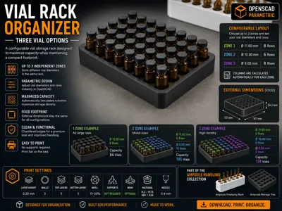
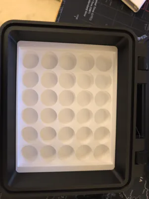
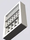
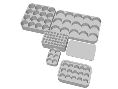
Parametric Multi-Zone Vial Tray (with Chamfer)
OpenSCAD parametric insert — configurable dimensions, wall thicknesses, chamfer, and up to three vial zones
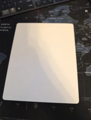
Designed to fit - https://makerworld.com/en/models/569039-lockable-rugged-tactical-utility-case#profileId-2811431
Description
A fully parametric OpenSCAD vial tray with configurable outer dimensions, wall thicknesses, bottom edge chamfer, and vial layout. The tray is divided into up to three independent zones, each holding a different vial diameter, so you can organise multiple vial sizes in a single insert.
The bottom edges carry a quarter-circle chamfer profile matched to the original tray-a.stl, so this tray sits correctly in the same case. The chamfer radius is a parameter — set it to 0 for a plain sharp-cornered box.
Everything is driven by a small block of variables at the top of the file — change a number, re-render, and the whole tray updates automatically. No manual geometry editing required.
Note - again this is designed to fit https://makerworld.com/en/models/569039-lockable-rugged-tactical-utility-case#profileId-2811431
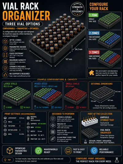
Key Features
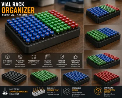
- Multi-zone layout 1, 2, or 3 independent vial zones in a single tray
- Per-zone vial diameter Set any diameter per zone; columns fill the usable interior width automatically
- Configurable row count Specify exactly how many rows each zone should have
- Independent outer wall thicknesses Set left/right (OWX) and front/back (OWY) outer wall thicknesses independently
- Configurable height Total tray height (CASE_Z) is freely configurable to match any case depth
- Chamfer on/off Quarter-circle chamfer on all four bottom edges matched to tray-a.stl at r=5 mm; set R=0 for no chamfer
- Dropped inner walls Outer walls at full CASE_Z; inner walls between holes drop to INNER_Z so vials are easy to grip
- Exact case fit XY footprint constrained to 131 × 167 mm — the tray will never exceed the case in plan
- Validation output Console echoes dimensions, wall margins, column counts, and vial totals after every render
Parameters
All user-configurable parameters are grouped at the top of the file under the USER CONFIGURATION section.
| Parameter | Default | Units | Description |
| NUM_ZONES | 3 | — | Number of active zones: 1, 2, or 3. Parameters for inactive zones are ignored. |
| Z1_DIAM | 24.05 | mm | Vial diameter for zone 1. Add 0.5–1 mm tolerance as needed. |
| Z1_ROWS | 2 | rows | Number of rows for zone 1 (Y direction). |
| Z2_DIAM | 15.0 | mm | Vial diameter for zone 2. Ignored if NUM_ZONES < 2. |
| Z2_ROWS | 3 | rows | Number of rows for zone 2. Ignored if NUM_ZONES < 2. |
| Z3_DIAM | 10.0 | mm | Vial diameter for zone 3. Ignored if NUM_ZONES < 3. |
| Z3_ROWS | 4 | rows | Number of rows for zone 3. Ignored if NUM_ZONES < 3. |
| WA | 1.2 | mm | Wall thickness between every pair of adjacent holes and between zone dividers. |
| OWX | 2.0 | mm | Minimum outer wall on left and right sides. Silently clamped to R if set smaller. Any grid remainder is added as inner margin on top of OWX. |
| OWY | 2.0 | mm | Minimum outer wall on front and back. Same rules as OWX. |
| CASE_Z | 34.2 | mm | Total tray height. Change freely to match your case depth. |
| INNER_Z | 24.2 | mm | Height of the inner walls between holes. Must be less than CASE_Z. Outer walls remain at CASE_Z. |
| SD | 1.0 | mm | Bottom thickness below the vial holes. |
| R | 5.0 | mm | Quarter-circle radius on all four bottom edges. Matched to tray-a.stl at 5.0 mm. Set to 0 for a plain box. OWX and OWY are clamped to this value as a minimum. |
CASE_X (131 mm) and CASE_Y (167 mm) are fixed constraints and should not be changed unless adapting the tray for a different case footprint.
How the Layout is Calculated
Understanding this helps you choose wall thicknesses and row counts that fit correctly.
Columns (X direction)
Columns are auto-calculated for each zone from the usable interior width:
usable_X = CASE_X − 2 × OWX columns = floor( usable_X / (vial_diameter + WA) )
Any X space left after fitting whole columns is split equally as additional inner margin inside OWX. The console reports this per zone.
Rows (Y direction)
You specify the rows. The tray fits them in sequence with WA-wide dividers between zones, then splits whatever Y remains equally as front and back margin inside OWY. If the inner Y margin goes negative your rows exceed the available space — reduce row counts until the console shows a positive value.
Height
Set CASE_Z to your case depth. INNER_Z controls how high the walls between holes rise. The gap (CASE_Z − INNER_Z) is how much of each vial protrudes above the inner walls for easy removal. Keep INNER_Z at least a few mm below CASE_Z.
Chamfer
When R > 0, the outer shell is built as a minkowski sum of a reduced inner box with a vertical cylinder of radius R and height R. This produces a quarter-circle profile on all four bottom edges and the correct corner geometry, while keeping the outer footprint exactly CASE_X × CASE_Y. OWX and OWY are clamped to R as a minimum because the chamfer zone requires solid material.
Instructions
- Set NUM_ZONES to 1, 2, or 3.
- Set the diameter and row count for each active zone (Z1_DIAM, Z1_ROWS, etc.). Add 0.5–1 mm to your measured vial diameter for a comfortable fit.
- Set OWX and OWY to your desired outer wall thicknesses. Both must be at least equal to R.
- Set CASE_Z to your case depth and INNER_Z to control inner wall height. INNER_Z must be less than CASE_Z.
- Set R to your desired chamfer radius, or 0 to disable the chamfer entirely.
- Render and check the console output — confirm the inner Y margin is positive and wall values look correct.
Suggested Print Settings
| Setting | Recommendation |
| Material | PLA or PETG |
| Layer height | 0.2 mm |
| Infill | 15–20% — the walls carry all structural load |
| Perimeters / walls | 3 or more for strong vial hole walls |
| Supports | None required — all overhangs are vertical |
| Orientation | Print flat (Z up), no rotation needed |
Tips & Notes
- Add 0.5–1.0 mm to your measured vial diameter. Print a single-hole test piece before committing to the full tray.
- The dropped inner walls (INNER_Z) expose any lip or flange at the top of the vial for easy removal.
- For a single vial size, set NUM_ZONES = 1 and configure only Z1_DIAM and Z1_ROWS.
- Zone order runs front-to-back: zone 1 is at Y=0, zone 3 is furthest back.
- OWX and OWY set the minimum outer wall. If the vial grid leaves extra X or Y space it is distributed as inner margin — the physical wall will never be thinner than OWX or OWY.
- The WA wall between zones is solid material and acts as a physical divider between vial sizes.
- Setting R = 0 disables the chamfer and produces a plain sharp-cornered box — useful if your case does not have a matching radius.
- With CASE_Z = 34.2 and R = 5.0 the outer profile exactly matches tray-a.stl and both trays can sit side by side in the same case.
- CASE_X and CASE_Y are fixed at 131 × 167 mm. Only CASE_Z is intended to be changed for different case depths. This is intended to fit - https://makerworld.com/en/models/569039-lockable-rugged-tactical-utility-case#profileId-2811431
Compatibility
Designed to fit the same 131 × 167 mm footprint as the original tray-a. With CASE_Z = 34.2 mm and R = 5.0 mm the outer dimensions and chamfer profile are identical to tray-a and both can be used side by side in the same case.
This is a REMIX of Customizable Vial Rack / Holder / Organizer by Flying4T
It is a specifically modified version of my own customisable three vial version https://makerworld.com/en/models/2567723-parametric-multi-zone-vial-tray-10ml-3ml-etc#profileId-2835115
It is intended to fit this lockable utility case https://makerworld.com/en/models/569039-lockable-rugged-tactical-utility-case#profileId-2811431
Thi
This remix is based on
License
You shall not share, sub-license, sell, rent, host, transfer, or distribute in any way the digital or 3D printed versions of this object, nor any other derivative work of this object in its digital or physical format (including, but not limited to, publishing derivative works outside the Makerworld platform or hosting on other digital platforms). The objects may not be used without permission in any way whatsoever in which you charge money or collect fees. Subject to the above restrictions, derivative works may be published only within the Makerworld platform, and all such derivative works must be licensed under the same SDFL‑C license, without modification or additional terms. You may download the digital versions of this object, 3D print it, and display images, videos, or usage demonstrations of 3D printed versions of the object on personal social media platforms or Makerworld official channels, provided that no digital versions of the object are shared or distributed.
Comment & Rating (0)