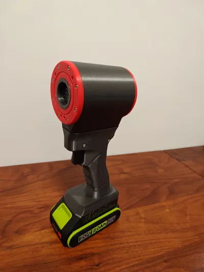
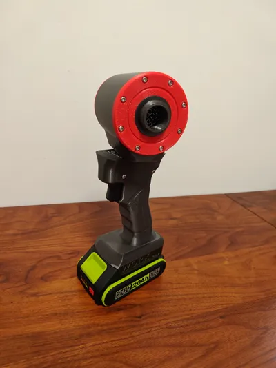
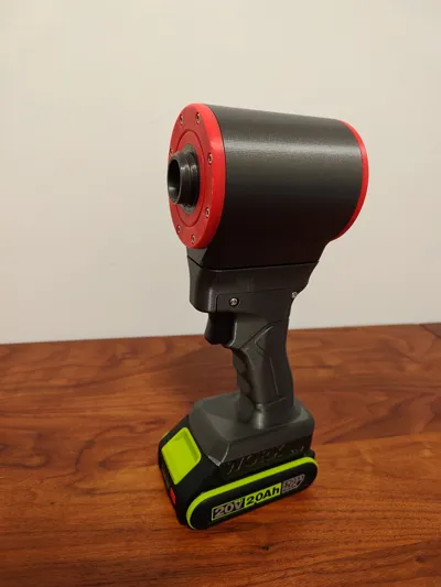
Laoge's Second Generation Flip Single/Dual Module Dyson V8 Motor Bi-directional Rotation Blower/Vacuum Handheld Turbo Blower/Vacuum Cleaner


Print Profile(3)

Description
This model is based on the model by @老哥 https://makerworld.com.cn/en/@laoge https://makerworld.com.cn/en/models/2203909 and has been modified
If you have already printed @老哥's second generation and want to adapt it to this model, you only need to print the two parts from the "main casing" plate in this model and replace the original main casing
If you find it interesting, please
Boost Me (for free)
Thank you very much!!!
--------------------------------------------------------------------------------------------------------------------------------
2026.05.21 Update:
Thanks to the selfless contribution of @BG5DDP for providing a highly compressed hinge base and main motor housing, which reduces the overall height by 10mm, making the whole more harmonious
It should be noted that the 4 screws for fixing the hinge need to be changed to flat head M4*6 screws

--------------------------------------------------------------------------------------------------------------------------------
2026.05.02 Update:
Problem description:
Many friends have encountered similar problems: pressing the trigger for a large initial section has no response, until it's pressed all the way down, directly triggering high speed. In normal operation, a slight press of the trigger should activate low speed, and pressing about halfway should activate high speed
Reason:
The trigger structure is likely different, leading to a change in the trigger's activation mechanism. Hereby, we condemn unscrupulous merchants who secretly swapped goods
Solution (Thanks to @佚拓达芬 for the solution and @小那 for verifying the solution):
Carefully disassemble the trigger and solder the two red-circled areas in the image below with wires:

After soldering, it looks as shown in the image below:


--------------------------------------------------------------------------------------------------------------------------------
Creative Idea:
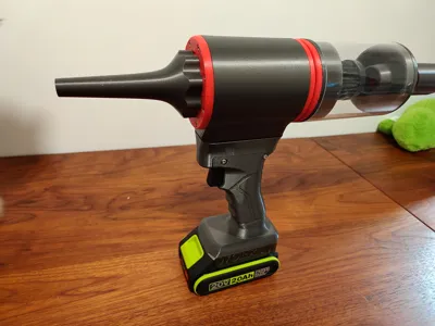
Having browsed through all the high-power fan models on the site, @老哥's design was my favorite. The ergonomic grip, elegant shape, reliable Dyson V8 motor selection, and the design for series-connected dual motors and both blowing and suction functions made me eager to print one
However, people are always greedy. I wanted one device to perform both blowing and suction, instead of printing and assembling two, or disassembling to reverse the motor direction
Of course, some other models on the site can meet the above requirements, but they generally have 3 problems:
- Most achieve blowing/suction switching by rotating the handle 180°, but when the handle is rotated 180°, the switch is also on the reverse side
- Most handles are generally cubic to accommodate a reverse grip, which doesn't feel as good as an ergonomic grip and cannot be paired with an ergonomic trigger
- Motors are generally unknown ducted fan motors
Overall, they are not elegant or reliable enough in all aspects. So, I came up with the idea of modifying @老哥's model:
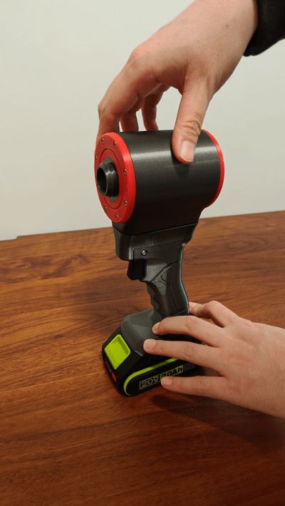
Can the head rotate without rotating the handle?
After extensive research, selection, and testing, this model was finally born
New Required Parts:
- A 180° limited damping hinge with wire routing holes, model selection:
Square 14 through-hole 1.5 pitch 180° (single-sided M4 thread) 19.3 shaft
The torque I bought was
0.1 N.m / (1 kgf.cm)
which felt too small but barely usable, and I was too lazy to change it. When purchasing, you can buy one with higher torque (thanks to @HANK's feedback, he bought a 0.5N.m one and still felt it was a bit small; @流川枫's feedback, he bought a 1N.m one and felt it was very suitable, requiring a slight effort, very stable, you can consider purchasing 1N.m or higher) for a better feel. Link as follows:
https://item.taobao.com/item.htm?id=776389306146&mi_id=0000hO3ExF-NIH6uH7igba76Y6IT_yZMqMGlby-RjPscTEs&sku_properties=1627207%3A32863654278&spm=tbpc.boughtlist.suborder_itemtitle.1.68ac2e8dxtVA6E

2. M4*10 countersunk screws required for hinge installation, and the corresponding L-shaped hex wrench. If you print the highly compressed version hinge base and main motor housing, the fixing screws must be changed to flat head M4*6


Installation Guide:
Basically, it's the reverse of @老哥's sequence, with the hinge installation inserted in the middle:
First, connect the trigger, MOS switch (it is recommended to protect it with heat shrink tubing), and power socket. Secure the power socket and handle with screws, paying attention to positive and negative terminals. Do not connect the motor or micro switch yet. For specific assembly, refer to @老哥's video and pictures (refer to the diagram below for circuit wiring, thanks to @HANK for the ingenious wiring diagram). Note: leave an extra 10cm of wire

Cut off the reinforcing rib in the middle above the trigger, as shown in the figure

Then solder the control wires to the micro switch as shown in the figure below. It is recommended to use heat shrink tubing

Insert the micro switch with the rotating shaft facing down, from the top surface when printing, into the corresponding position of the hinge base. Make sure to press it all the way down, ensuring the plastic body of the micro switch is lower than its surrounding surface

Insert the more prominent side of the hinge cylinder, which is the metal plate with the countersunk hole, into the flat side of the hinge base (the bottom surface when printing), and fix it with M4*10 countersunk screws

The screws must be tightened completely, without interfering with the opposite metal surface

Connect the other side of the hinge to the main motor housing, screwing in from inside the motor compartment

After tightening, turn it over and rotate the grip and motor housing to about 90° in the middle. Check if the screws in the motor housing are tightened all the way. Ensure the screws are deeply threaded into the metal plate

- This step is important. Do not rush to fix the connection between the grip and the hinge base. Instead, first pre-assemble the motor into the motor housing to confirm if the power and control wires are long enough. The standard for being long enough is that the control wire can loop around the gap in the hinge base, as shown in the image in step 4, and the power wire likewise
After confirming the wires are long enough, install the motor, trim the power and control wire lengths, attach copper terminals to the power wires, and solder the control wires to the motor (I forgot to take a photo here, so I'm using one of @老哥's pictures)

Ensure that the reserved wire length is not inside the motor compartment, but rather inside the hinge base. Clip in the motor retainer, and fix the front and rear covers of the motor with screws
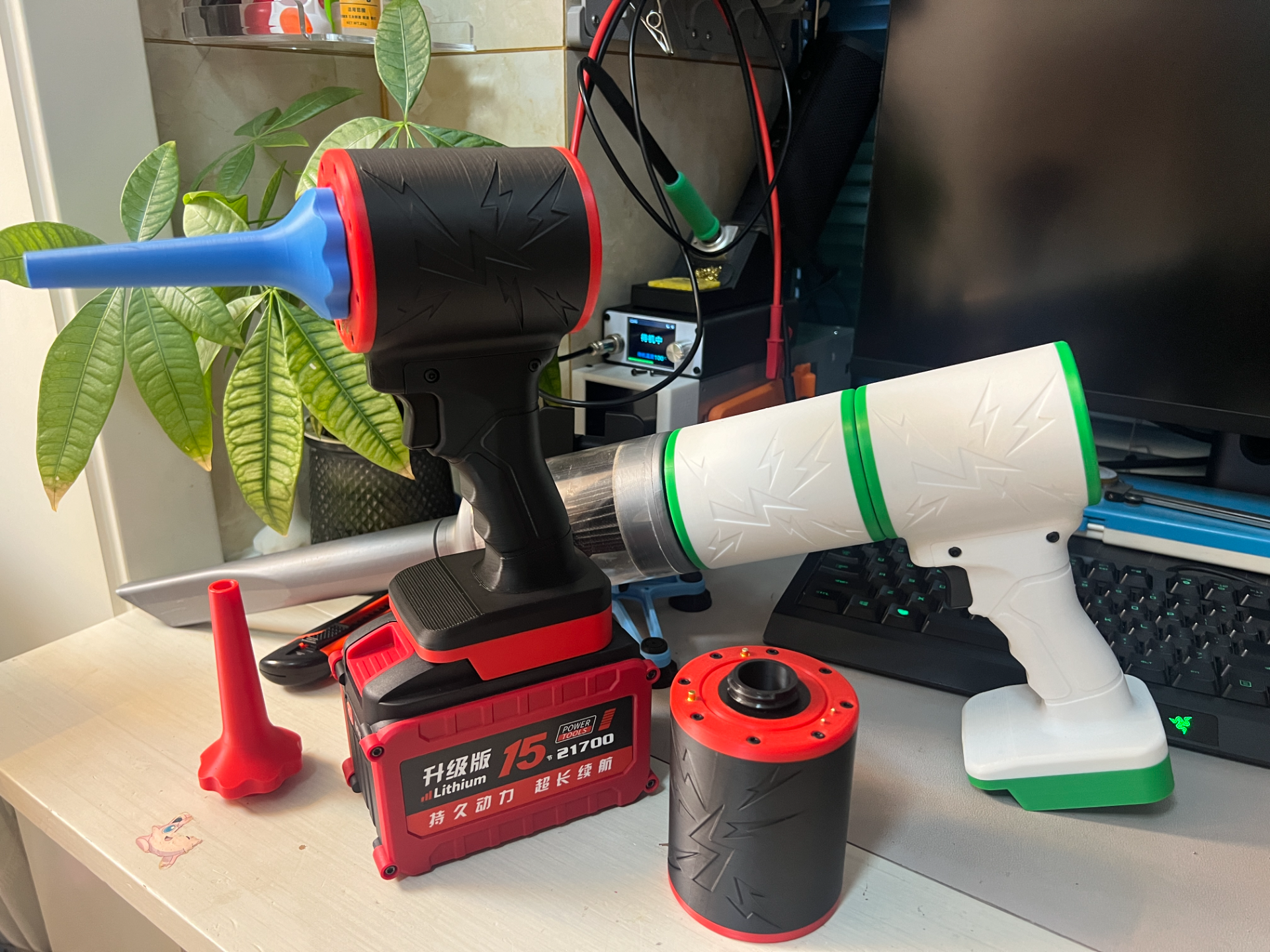
I made a small modification here: since the blowing/suction function can now be switched by rotating the head, for easier distinction, I replaced the thread on the motor cover of the blowing side (i.e., the side with the motor and circuit board) with an external thread (i.e., the thread protrudes from the motor cover). Correspondingly, the nozzle was changed to an internal thread. I personally think this is more intuitive: the suction part is concave, and the blowing part is convex. The same applies to independent motors


Fill the wire routing holes of the hinge with hot melt glue to prevent air leakage and secure the wires. Note that the hot melt glue should only secure the wires in the green-circled area in the image below, which are the parts that rotate synchronously with the motor housing. Do not get it on the more external wires, such as those in the yellow-circled area, as this will affect rotation
PS: In this step, the power wires also need to be handled similarly. Since it's inconvenient to photograph, only the control wires are shown in the image below; please understand the intent

- Connect the grip and hinge base with screws
Installation complete!! Hope everyone enjoys it~~
This remix is based on
License
You may create derivative works based on this object, provided that all such derivative works are published exclusively on the MakerWorld platform and include proper attribution to the original creator. You may not share, upload, host, distribute, or publish this object—or any derivative work of this object—on any other digital platform, marketplace, or distribution channel. Commercial use of this object and any derivative works is strictly prohibited. This includes, but is not limited to, selling, renting, sublicensing, or using the object in any context in which you receive monetary compensation or other financial benefits.
Comment & Rating (1)