
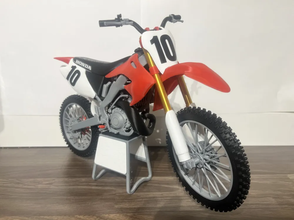
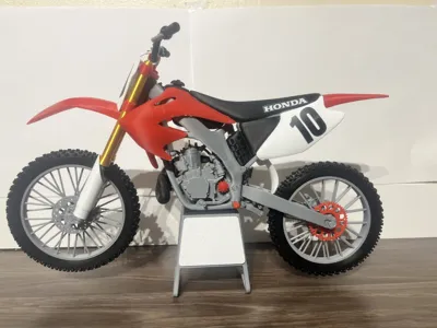
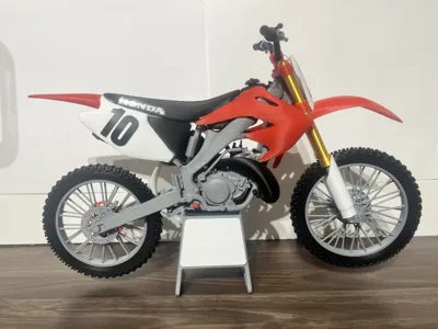
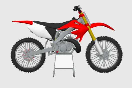
HONDA CR250R
Print Profile(4)

Description
Boost Me (for free)
IF YOU LIKE MY MODELS PLEASE BOOST ITS FREE
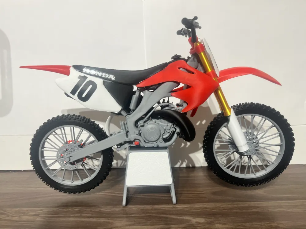
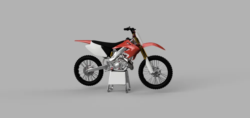
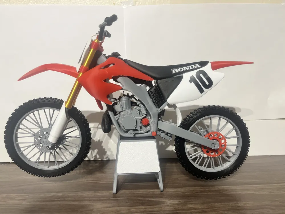
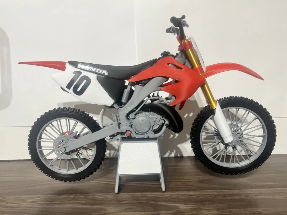
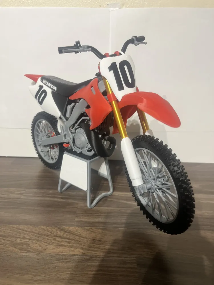
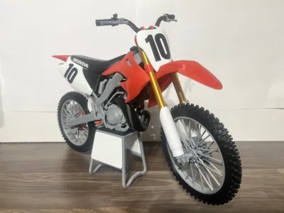
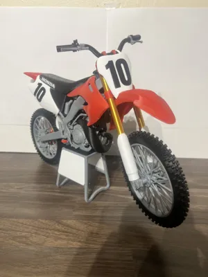
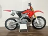
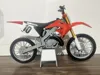
HONDA CR250 MODEL
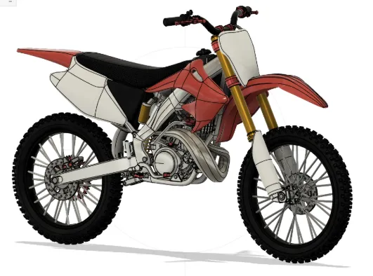
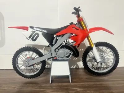
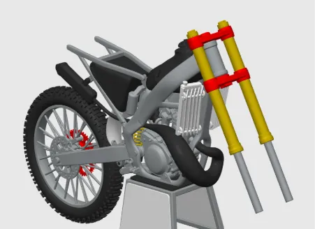
This is a 1/6 scale model of a Honda CR250R 2007 motocross bike with rotating wheels, pivoting swingarm and spring loaded front and rear suspension, 84 pieces Length 325MM Hight 200mm Width 110mm.
Feedback is greatly appreciated! Please boost my model
Pre-assembly:
Some parts may need sanding/filing before assembly to ensure a perfect fit.
**(Make sure to clear all supports)**
Tools needed:
Drill bit. (2mm, 2.5mm, 3mm, 4mm)
- Glue.
- Rasp/small file or sandpaper.
- Springs:
Fork springs: (Outer diameter 5mm, length 60mm x2)
Rear shock spring: (Outer diameter 8mm, length 40mm) (DO NOT GET SPRING STEEL)
**(Drill bits to be used only by hand or pliers to prevent damage to parts)**.
Assembly guide:
Step 1
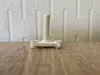
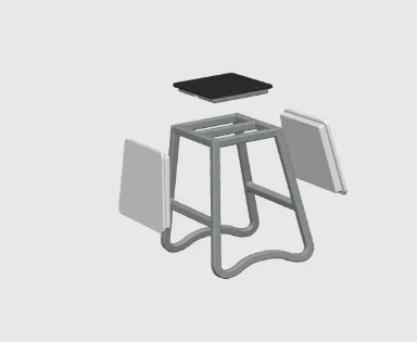
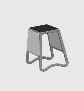
Glue the top plate and side panels to the stand.
(As shown below)
Step 2
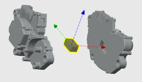
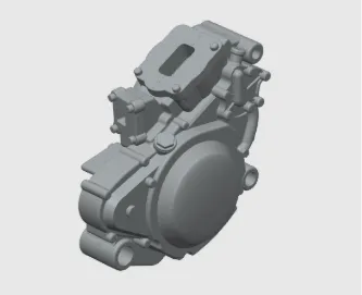
Use the connecting block to join the left and right side of the engine, use some glue if needed.
(As shown below)
Step 3
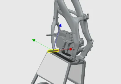
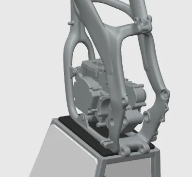
Slide the engine pins into position and glue in place. Use 2mm & 3mm drill bit to clear holes.
Pin size. 18mm x 2mm
22mm x 3mm
(As shown below)
Step 4
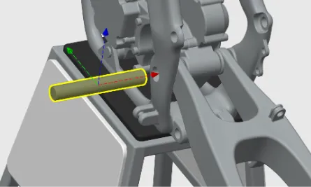
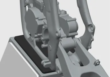
Place the swingarm in position then slide the pin into place and glue in place, use a 4mm drill bit if needed.
Pin size
26.5mm x 4mm
(As shown below)
Step5
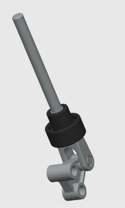
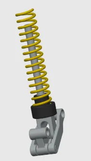
Rear Cushion Setup
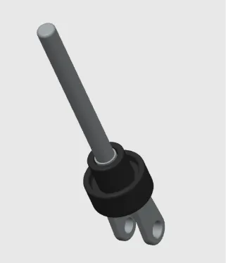
Slide the spring cup into position on to the rod, next secure the link in place with the pin. Use a 2.5mm drill bit to clear holes in the link.
Pin size
6.8mm x2.3
(As shown below)

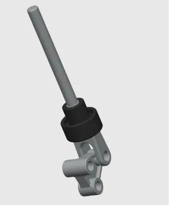
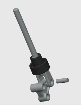
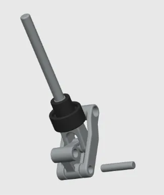
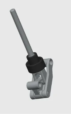
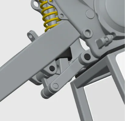
Next, put the second link in position and secure it in place with pin.
Pin size
11mm x2.3mm
(As shown below)
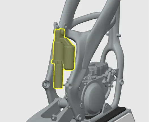
Step 6
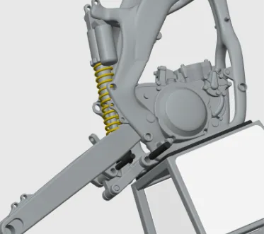
Clip in place the rear suspension body.
(As shown below)
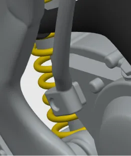
Next, slide the spring on to the rear cushion assembly, then attach to the rear suspension body, swingarm and frame using pins.
Pin size
16mm x 2.3mm
16.5mm x 2.85
(As shown below)
Step 7
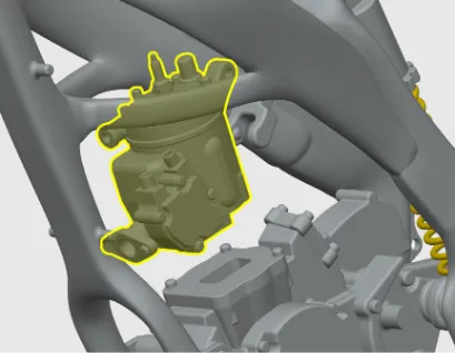
Glue in place the cylinder head.
(As shown below)
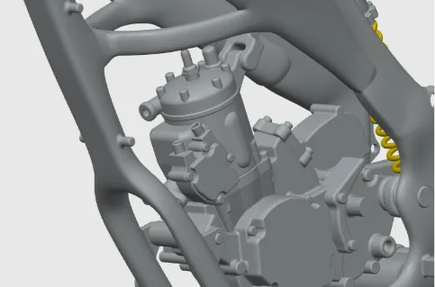
Step 8
Glue the carburetor in place.
(As shown below)
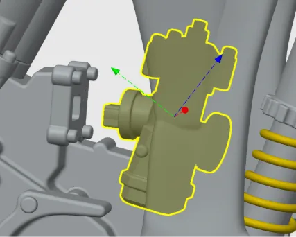
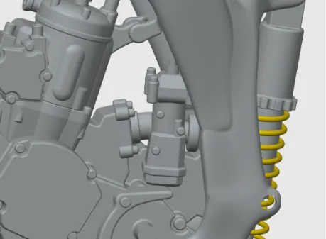
Step 9
Attach the sub frame to the frame.
(As shown below)
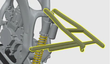
Step 10
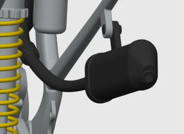
Attach the expansion chamber to the cylinder head and frame using glue.
(As shown below)
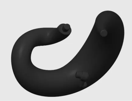
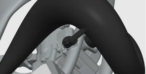
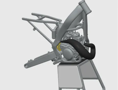
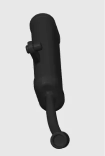
Then attach the muffler to the expansion chamber and sub frame using glue.
(As shown below)
Step 11
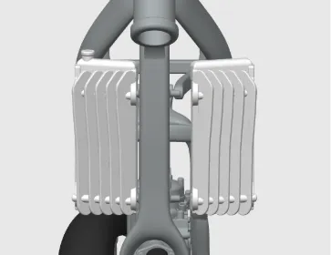
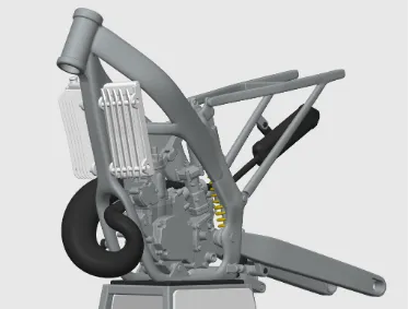
Glue in place the radiators.
(As shown below)
Step 12
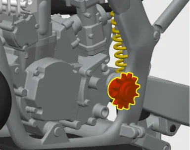
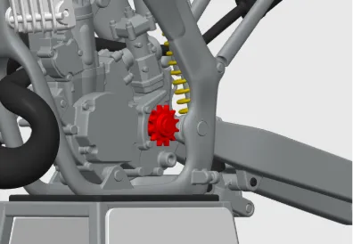
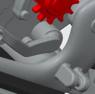
Push on the front sprocket.
(As shown below)
Step 13
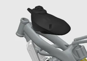
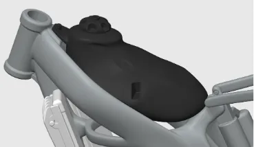
Push the fuel tank in place.
(As shown below)
Step 14
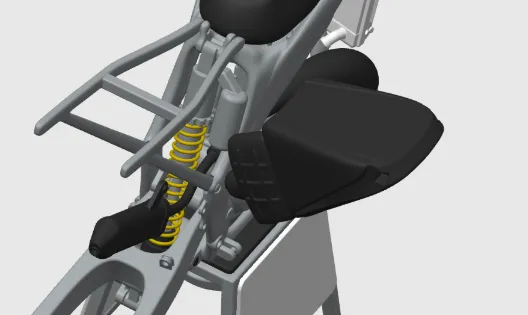
Slide the airbox through the Right side of the sub frame and round the rear suspension into the carburetor, glue in place if needed.
(As shown below)
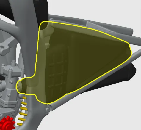
Step 15
Glue the rear mud flap to the air box.
(As shown below)
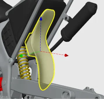
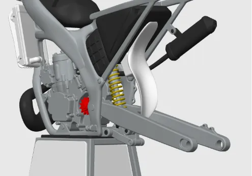
Step 16
Wheel Assembly
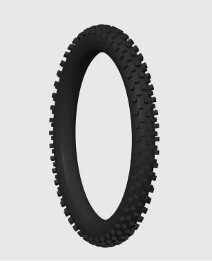
Glue the two halves of the tyres together using the blocks.
(As shown below)
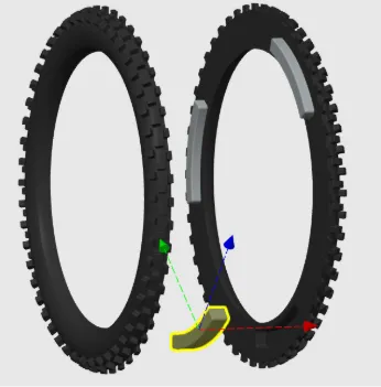
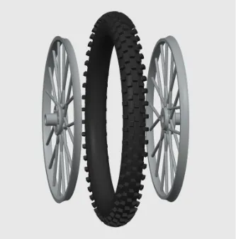
Next Glue the two halves of the rim together.
(As shown below)
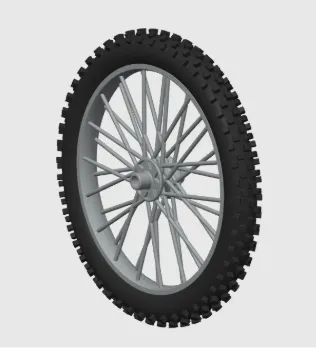
Repeat the last step for the other wheel
Step 17
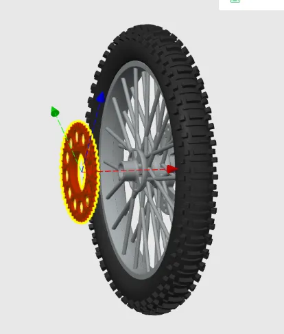
Next Slide the rear sprocket onto the left side of the rear wheel and the rotor onto the right side, rotor on left side of the front wheel.
(As shown below)
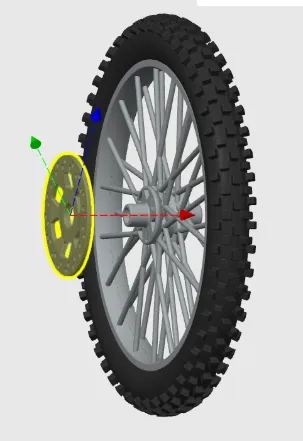
Step 18
Glue in place the rear Caliper then position the rear wheel and secure in place with the rear axle.
(As shown below)
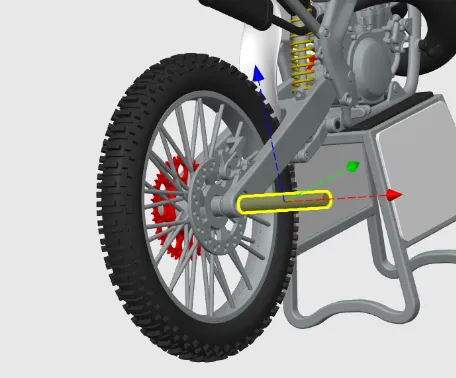
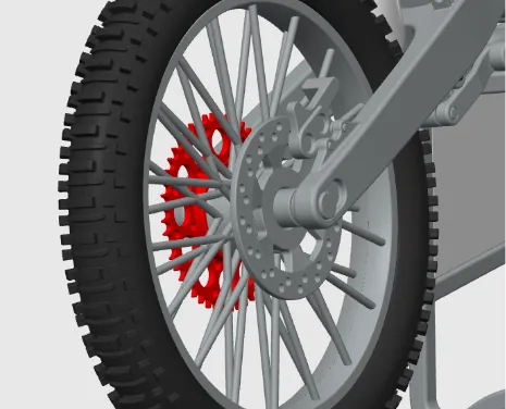
Step 19
Fork Setup
Feed the stanchion into the fork body smaller end first, then slide in the springs and secure in place with the fork caps.
(As shown below)
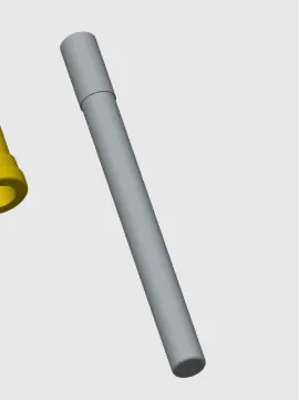
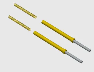
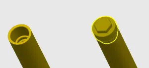
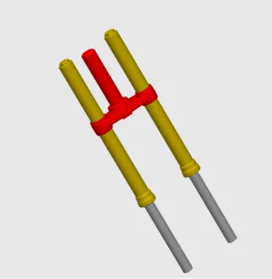
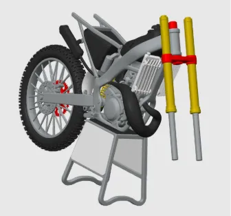
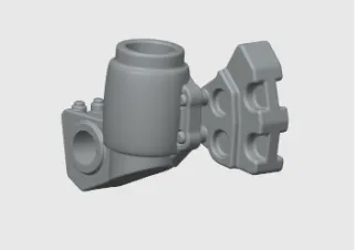
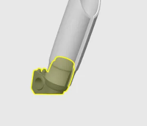
Next, slide the fork crown onto the suspension body, then feed the fork crown through the frame and secure it in place with the top clamp.
(As shown below)
Step 20
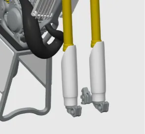
Glue the front caliper to the fork shoe and push the fork covers onto the shoe then assemble to the forks.
(As shown below)
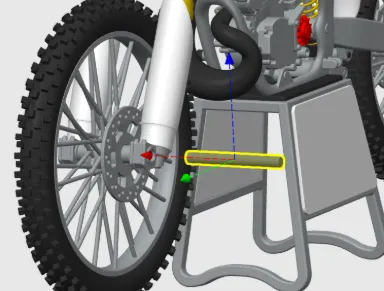
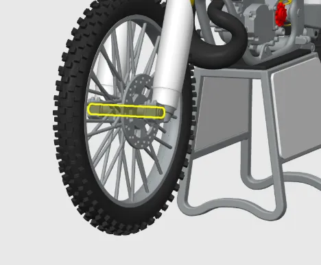
Step 21
Position the front wheel and secure in place with the front axle.
(As shown below)
Step 22
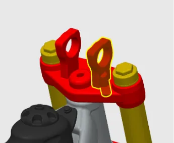
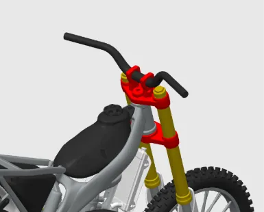
Push in the two handlebar mounts then slide the bars through.
(As shown below)
Step 23
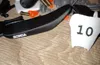
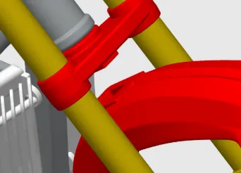
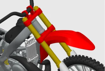
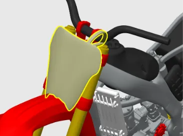
Glue in place the front mud guard then feed the number plate on to the bars and glue to the front mud guard and forks.
(As shown below)
Step 24
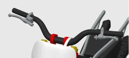
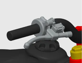
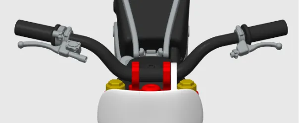
Slide the brake lever, throttle and clutch lever onto the bars then push on the grips.
(As shown below)
Step 25
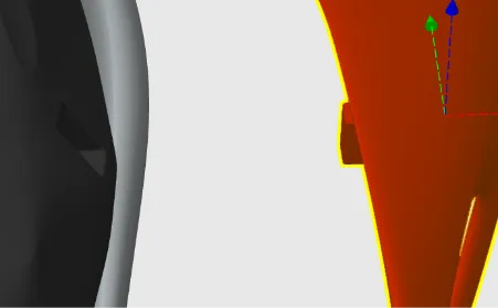
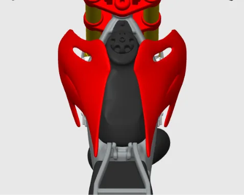
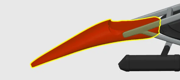
Glue in place the front fearing and the rear mud guard.
(As shown below)
Step 26
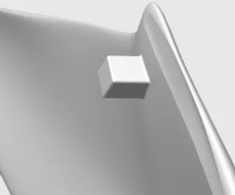
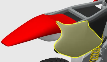
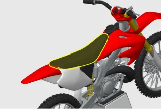
Glue the rear side panels to the air box then glue in place the seat.
(As shown below)
Step27
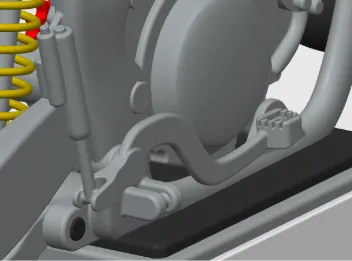
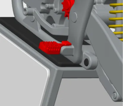
Glue in place the gear lever, foot brake, kick start and pegs.
(As shown below)
Enjoy!
Documentation (1)
License

You shall not share, sub-license, sell, rent, host, transfer, or distribute in any way the digital or 3D printed versions of this object, nor any other derivative work of this object in its digital or physical format (including - but not limited to - remixes of this object, and hosting on other digital platforms). The objects may not be used without permission in any way whatsoever in which you charge money, or collect fees.


Comment & Rating (73)