Kawasaki Ninja 1000SX/1100SX Button


Print Profile(1)

Description
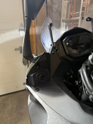
This project allows you to add a button to your Ninja 1000SX/1100SX to the existing hole left of the screen for the optional DC Power outlet add on, Kawasaki part # 99994-1413. In my case, I used the button to operate a garage door opener remote to close the garage when I leave and open it when I return. This can be adapted to other mods such as additional lighting or any other electronics add on that would use a button.
The printed parts include:
- A “plug” (not sure how else to describe it) that the button threads into
- A nut for securing the “plug” to the black plastic trim
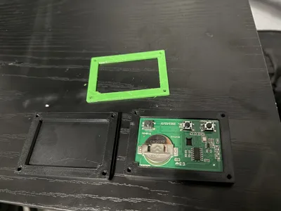
- Case lower half to contain the garage door opener remote board
- Case upper half
- TPU gasket for water proofing
I printed in ABS. The tolerances are a little tight on the case with ABS, so you may need to scale up 1% or so on the three files specific to the case. The “plug” and nut were a perfect fit for me as is.
Link to the button used: https://www.amazon.com/dp/B07NZDW47Q?ref=ppx_yo2ov_dt_b_fed_asin_title&th=1
Any similar button threaded at m16x1 would probably also work as it is modeled for the button to thread directly into the print.
Link to garage door opener remote used:
https://www.amazon.com/dp/B09NW7RFV1?ref=ppx_yo2ov_dt_b_fed_asin_title&th=1
To install the button, the left side middle fairing needs to be removed. Here is a good video guiding you through the process:
Also, remove these two screws with an m4 hex key or hex socket to be able to pull out the black plastic trim to gain access behind it:

There is a single Phillips screw behind the blank hole cover that comes on the bike. Use a short Phillips screwdriver to remove.
The main board of the garage door opener remote needs to be removed from it's case that it comes in. Just separate the halves with a flat head screw driver or even the metal clip it comes with can be used.
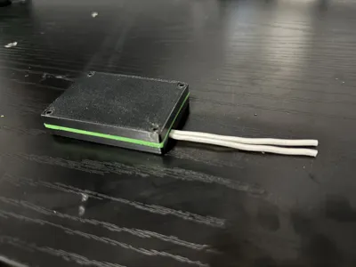
Before placing the main board into the case, solder two wires to diagonal leads of the single button closest to the exit hole on the case. It doesn't matter which pair you use as long as they are diagonal to each other so either choose the leads circled in blue OR the leads circled in red indicated below. I personally did the red leads. Then put the main board in the bottom half of the case. Start by feeding the wires through the hole in the bottom half of the case. Hot glue can be used around the wires on the outside of the case for water proofing.

Place the TPU gasket on the bottom half, and the top half on the gasket. Using M3x8mm socket head screws, sandwich the halves together. The TPU gasket is green in my case:

To install on the bike:
- I used some strong velcro to mount the remote to the underside of the black trim
- When mounted, put the wires through the nut so the nut is hanging under the trim
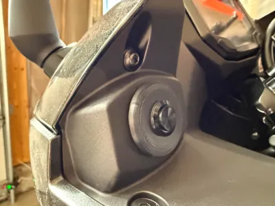
- Feed the wires up and out of the hole where the button will go
- Pay attention to the orientation of the printed part. There is an indentation that needs to face upwards to fit properly into the hole
- Secure the wires into the leads on the back of the button using a small Phillips screwdriver. It does not matter which wire goes to which lead
- Place the button in the hole and thread the nut into the back of the printed part to secure in place

Put everything back together and enjoy!
Comment & Rating (0)