
PTFE connector clip for A1
Print Profile(1)
Bill of Materials



Description
No generative AI has been used at any stage in making this post. These words and the design itself are mine.
Boost Me (for free)
Hey, thank you so much. I really appreciate it!
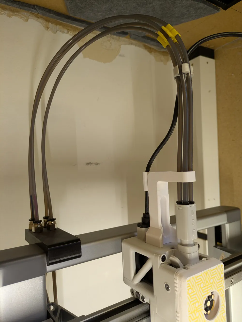
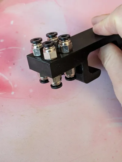
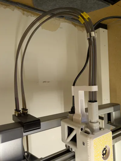
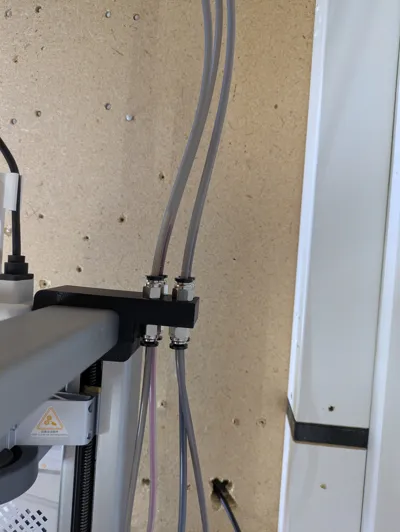
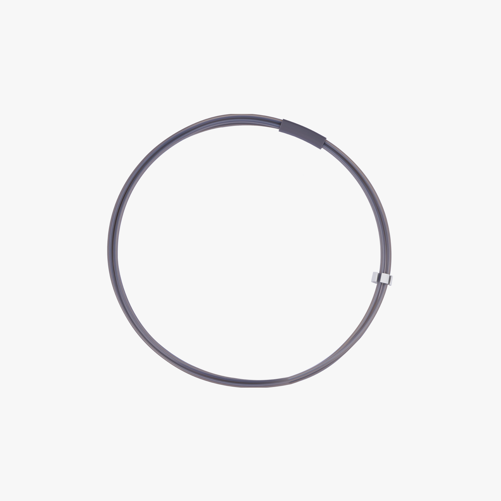
Clip that helps route PTFE tubes to your printer. Since I've got my A1 in an enclosure, I can't fit the AMS lite or connect filament tubes between it and the toolhead without causing trouble and making everything a hassle whenever I need to do maintenance. With this attachment, I can keep the tubes to the toolhead at a constant length that I know works well, and still detach the printer from my filament managment without disturbing the printer setup itself.
The model clips on to the top rail of the Bambu Lab A1 printer (I got the dimensions of the rail from this forum post), no hardware required. You should print this in PETG, as it's got enough flex to clip into place without breaking, while still allowing for tight tolerances.
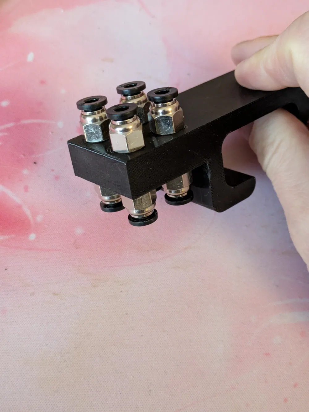
You will need two PC4-M6 pneumatic couplers per PTFE tube, make sure you use ones with a wide enough inner diameter, so that you can push the tubes through and make them touch between the two couplers. With smaller inner diameters, I found that filament would get stuck as it always has a bit of a curve from the spools.
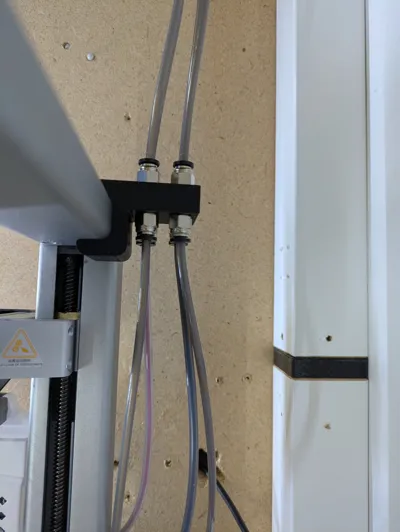
There are some really good models on makerworld that have the tubes mounted horizontally. While they are great for their usecases, I found that such a configuration sacrificed too much build volume. In my experience, routing the PTFE tubes vertically affords a bend that is closer to how the AMS lite is supposed to connect to the toolhead out of the box.
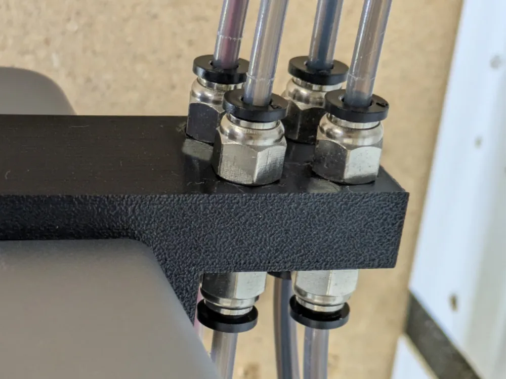
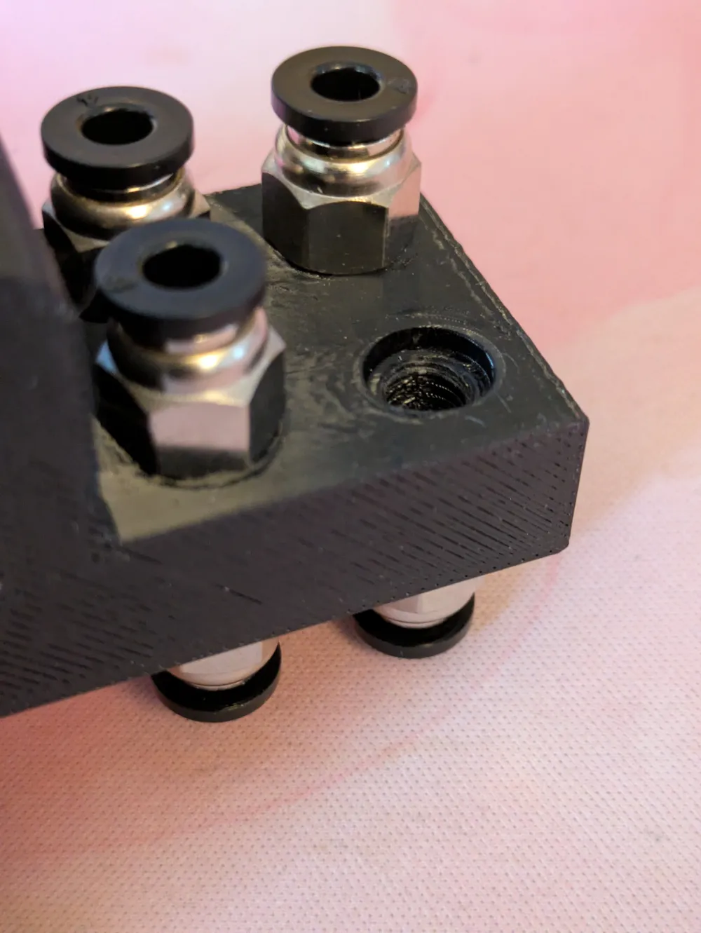
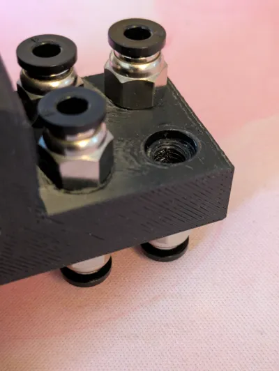
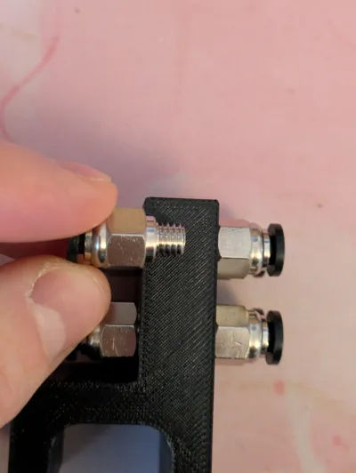
| The fit is tight by design. You're going to need a spanner or wrench to screw these in. I have added an indentation to the holes that help the couplers align. Without them, everything inevitably ended up kinda crooked. | 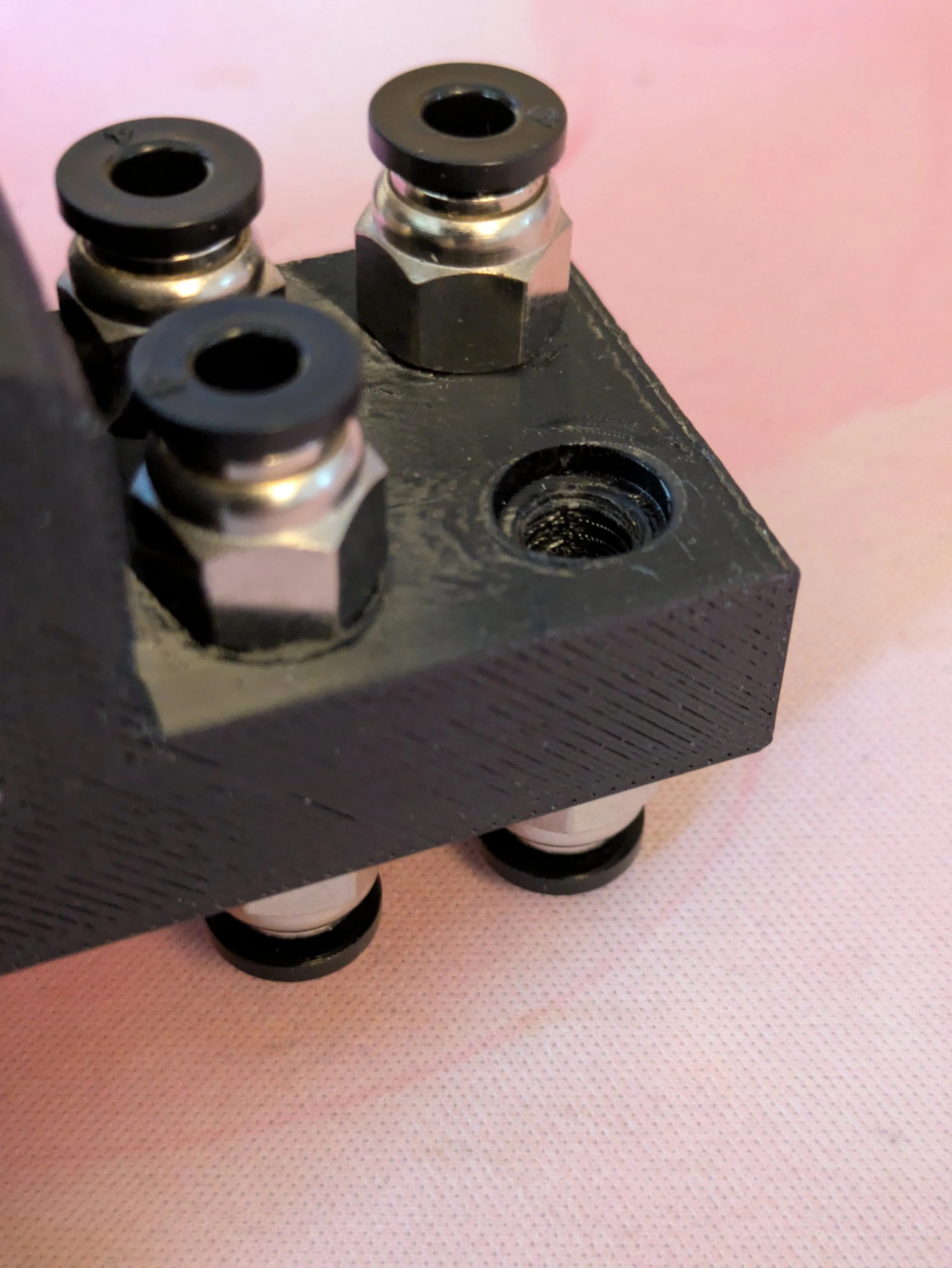
|
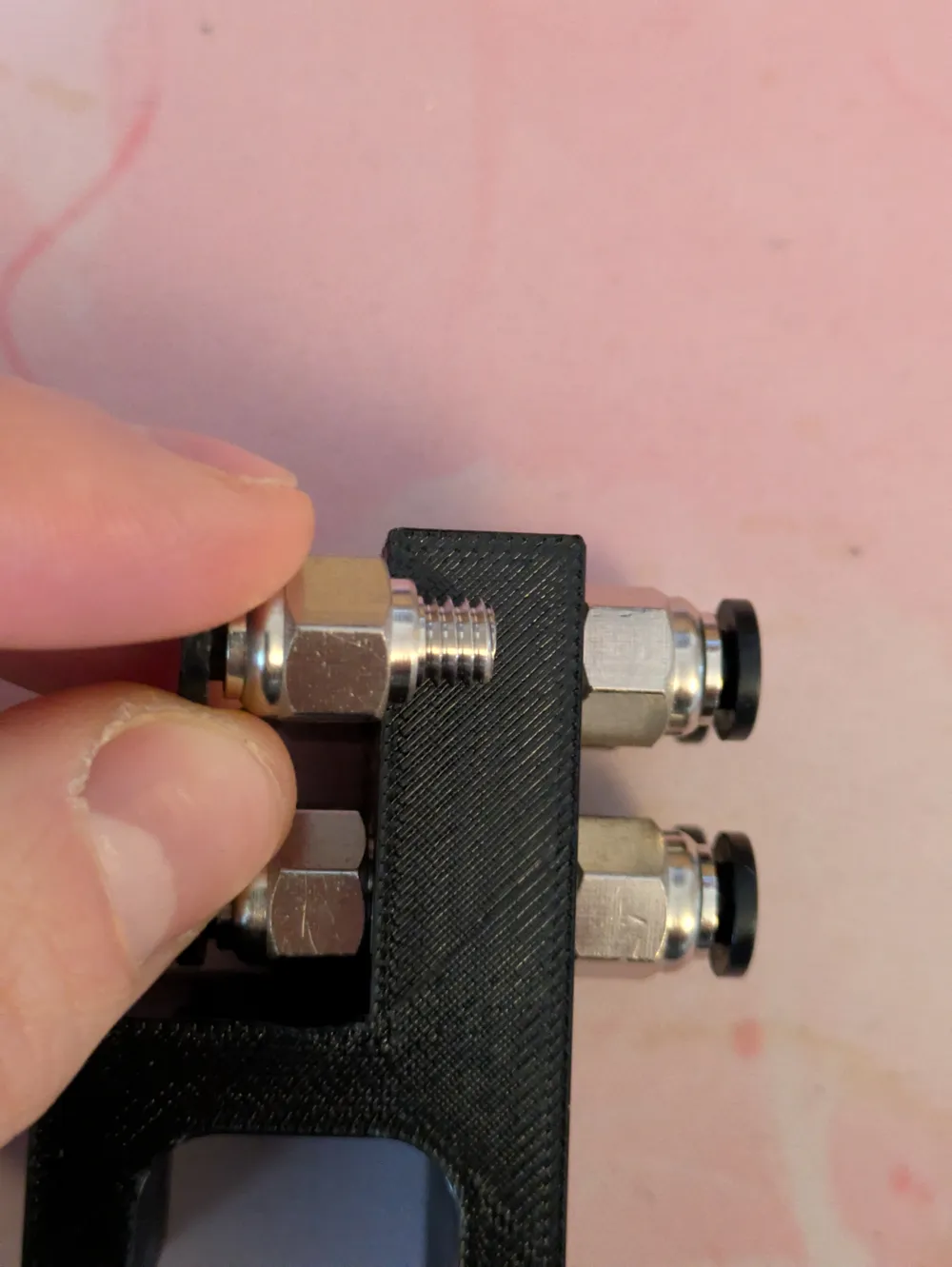
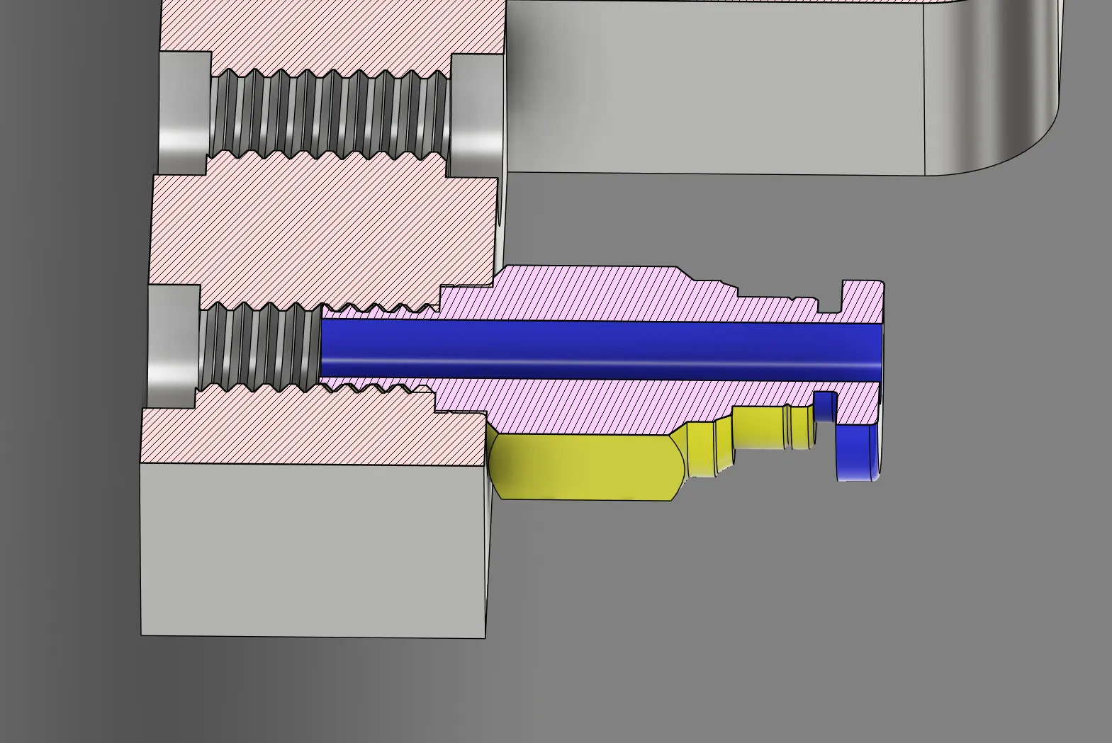
| As you can see, the fittings should bump against each other when they're fully screwed in. Depending on your specific printer, filament, and fittings, you might not be able to screw both fittings in so they sit flush with the clip. This is intentional, as I didn't want there to be a gap between the fittings. When they sit up against each other, the filament no longer got stuck when I tested and prototyped the model. | 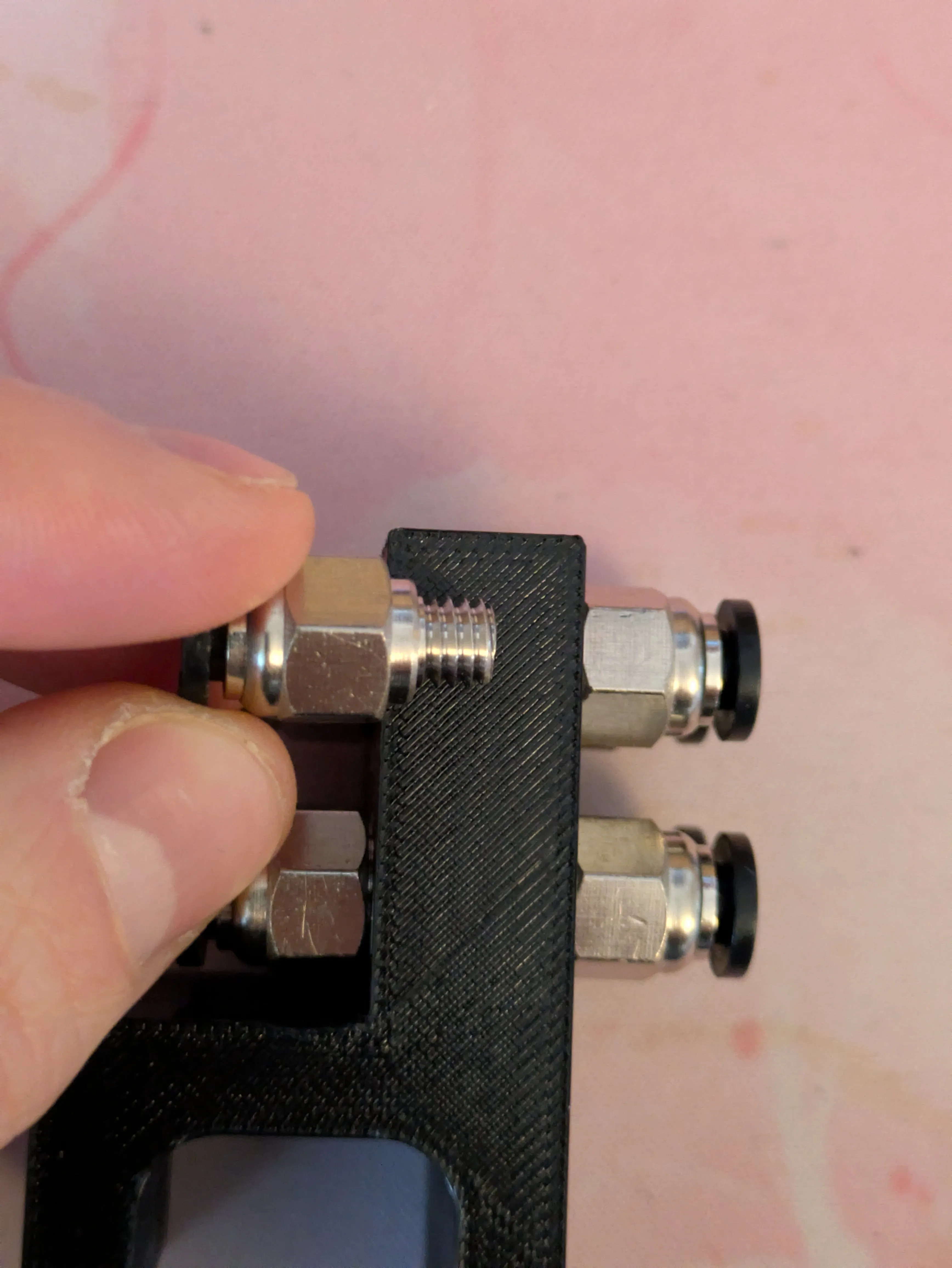
 |
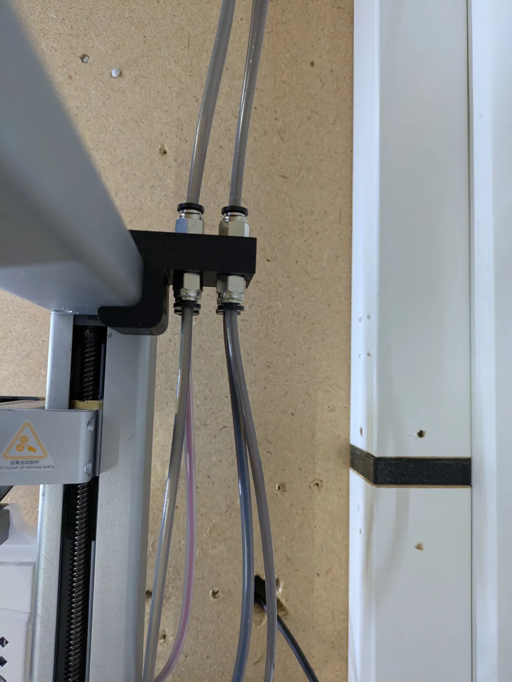
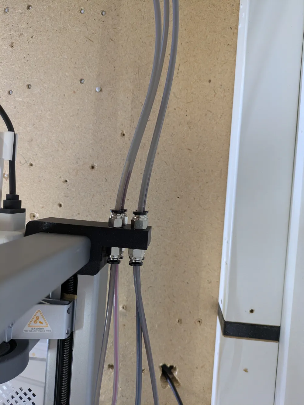
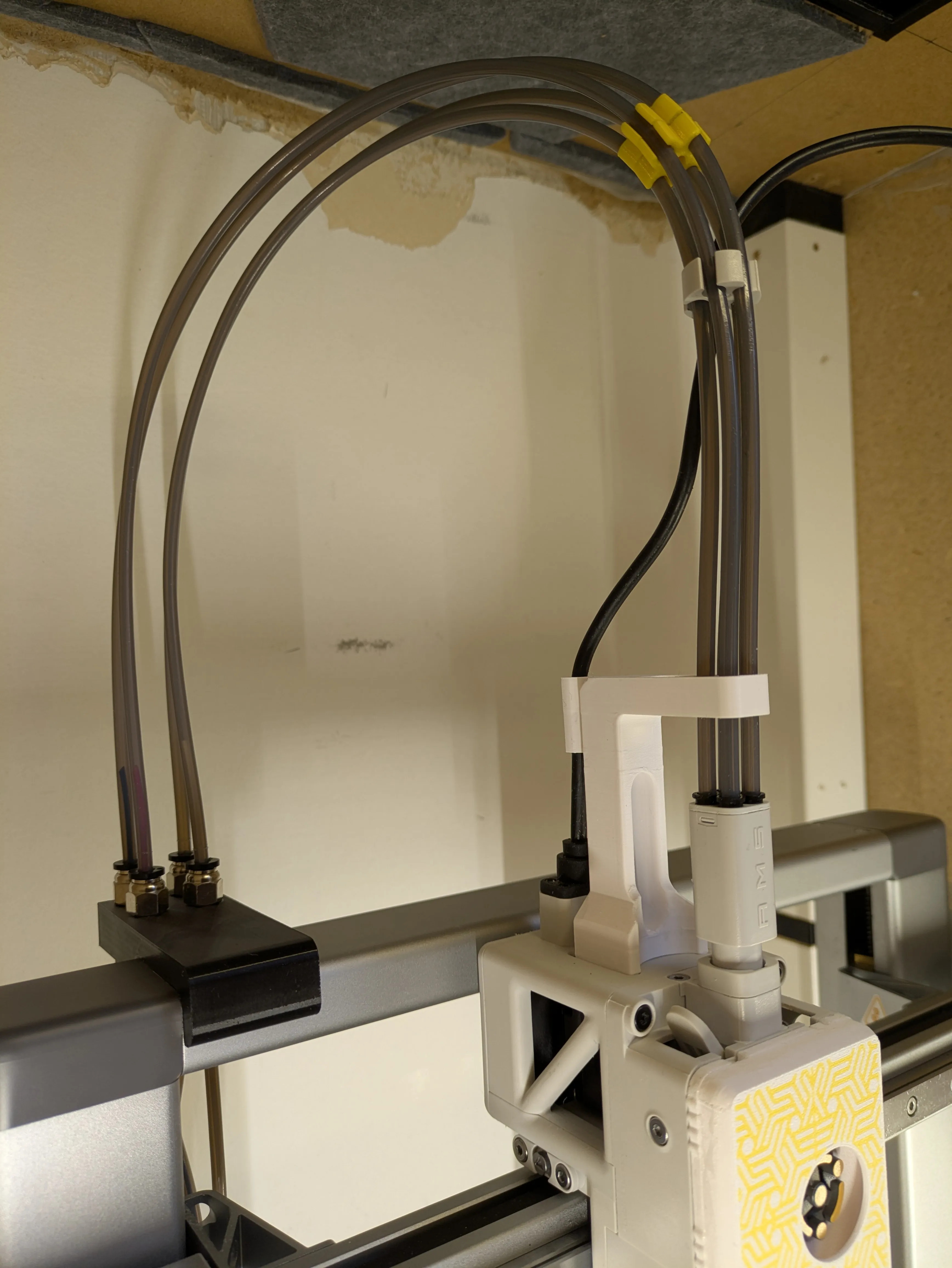
| I keep the clip as far as I can to one side on the rail. This way, the tubes coming from underneath don't interfere with the print area at all. Of course, they portrude a bit below the fittings, but it should still be possible to route them to the side without bending them aggressiively and still remain above the nozzle when the printhead is at its maximum Z-position. |
|
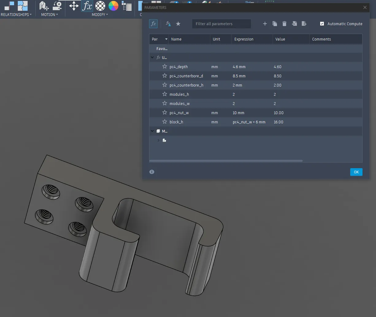
| I have included the Fusion files too. They are parametric and you should be able to customise the tolerances and number of fittings just using the user parameters. Your mileage may vary, but it's worked without breaking for me so far. |
 |
License



Comment & Rating (3)