Desk Power Station & Strip - PCE Industrial Grade


Print Profile(1)
Description
Industrial Modular Power Station - PCE Edition (High-Power Engineering Grade)
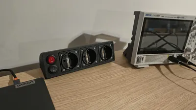
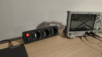
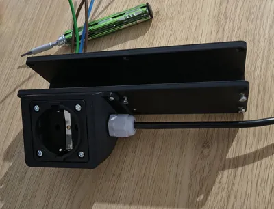
Transform your workspace with a heavy-duty, modular power distribution system designed for engineers, makers, and lab environments. This isn't just another plastic box; it’s a high-performance power hub built around professional PCE Schuko sockets and industrial-grade internal wiring.
Key Features & Advantages:
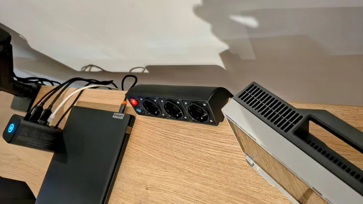
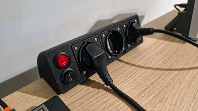
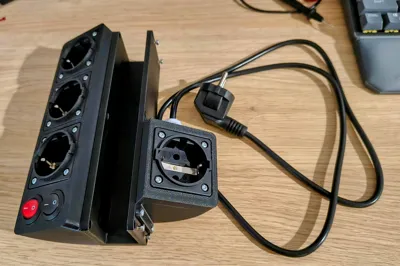
- Dual-Section Control: The smart modular design features two independent sections. The main switch controls the top 3-socket rail (perfect for bench equipment), while the second switch activates the hidden under-desk module.
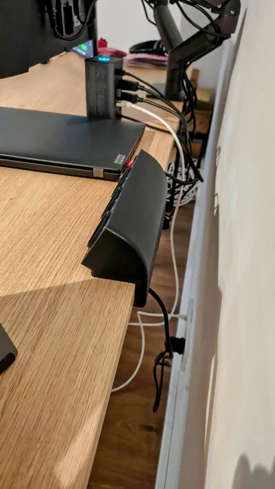
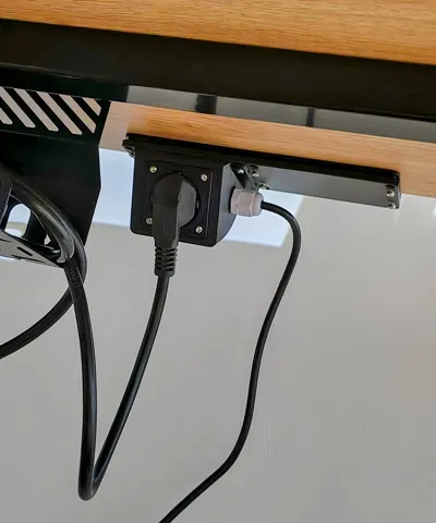
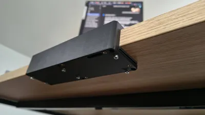
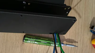
- Non-Invasive C-Clamp Mount: Securely attach the station to your desk without drilling any holes. The robust C-Clamp system is designed to be rock-solid while protecting your furniture (includes a dedicated desk protection pad).
- Universal Desk Support (Multi-Size C-Clamp) This project now supports a wide range of desk thicknesses! I’ve designed dedicated C-Clamp brackets for:
- 18mm & 20mm: Standard office furniture and plywood.
- 25mm & 30mm: Solid office desks.
- 34mm & 35mm: Popular IKEA (Linnmon/Lagkapten) series.
- 40mm: Heavy-duty workbenches and kitchen-top desks.
All versions are available in both .STL (for quick printing) and .STP (for easy CAD remixing).
- Engineering Grade Durability: Designed for M3 heat-set inserts (32 points of contact!), ensuring that gnarled threads or loose sockets are a thing of the past.
- Professional Aesthetics: Looks perfectly at home next to high-end lab gear like oscilloscopes or power supplies.
Bill of Materials (BOM) - Full Technical List
| Part Name | Qty | Manufacturer / Code | Original TME Shop Link |
|---|---|---|---|
| Schuko Socket (PCE) | 4 | PCE 10584-0s | Direct Link |
| M3 Threaded Inserts | 32 | Bossard B3/BN1054 | Direct Link |
| Screws (Socket/Housing) | 26 | Bossard 5001994 (M3x6) | Direct Link |
| Screws (Main Structure) | 6 | Bossard 3108710 (M3x8) | Direct Link |
| Main Switch (Red LED) | 1 | SCI R13-112BF-02-BR | Direct Link |
| Sub-Module Switch | 1 | SCI R13-112F-02-BB | Direct Link |
| Crimp Terminals | 5 | TE 1-160304-0 | Direct Link |
| Wire Ferrules (8mm) | 8 | TE 966144-4 | Direct Link |
| Wire Ferrules (Secondary) | 4 | TE 1241002-1 | Direct Link |
| Cable Gland (PG9) | 1 | Kradex ZCG PG9-8 | Direct Link |
| Wire 1mm² (Brown) | 1m | Helukabel 64110 | Direct Link |
| Wire 1mm² (Blue) | 1m | Helukabel 64109 | Direct Link |
| Wire 1mm² (PE) | 1m | Helukabel 64108 | Direct Link |
| Heat Shrink (with glue) | 1m | CYG/KTG CB-DWT(3X) | Direct Link |
🔩 Crucial: C-Clamp Tightening Screws As shown in the assembly photos, the 6x M3x8 screws are specifically required for the C-Clamp mechanism. They pass through the structural desk-clamping plate.
- Warning: Standard M3x6 screws are too short for this part of the assembly.
- Recommendation: For the best experience, just use M3x8 for everything (32 pcs). They provide deeper thread engagement and ensure the station stays rock-solid on your desk even under heavy load.
Assembly Tips: Heat-Set Inserts


To achieve the intended structural strength, the 32x M3 inserts must be installed correctly:
- Tool: Use a soldering iron with a standard conical tip (or a dedicated heat-set insert tip).
- Temperature: Set your iron to approx. 200°C – 250°C (depending on the material: PET-G/ASA).
- Technique: Gently press the insert into the pre-modeled hole. Let the heat do the work—do not force it. Ensure the insert is flush with the plastic surface.
- Alignment: Keep the iron vertical to ensure the threads stay perfectly straight for the final assembly.
Insert Map & Placement: With 32 mounting points, precision is key. Please refer to the "Insert Map" images to identify all 32 locations:
- PCE Sockets: 16 points (4 per socket) ensure the sockets won't budge even with heavy industrial plugs.
- Main Housing & Structure: 16 points to keep the entire frame, covers, and C-Clamp rock-solid.

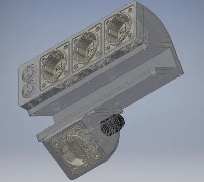
🛠️ Visual Assembly Breakdown . To make your build as easy as possible, refer to the partial exploded view above.
- The Blue Trails: These lines show the exact alignment for all screws and heat-set inserts. No more guesswork!
- Modular Structure: You can clearly see how the main station core, the modular side-enclosures, and the structural C-clamp plate integrate into a rock-solid unit.
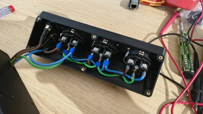
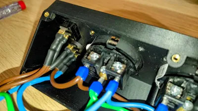
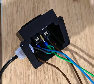
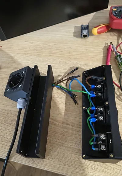
Electrical Wiring & Assembly

The station features a professional independent circuit design as shown in the schematic above.
- Independent Logic: The top rail and the under-desk module operate on separate circuits, allowing you to cut power to your bench tools while keeping under-desk equipment (like a 3D printer or server) running.
- Color Coding: The schematic follows standard European wiring: Brown (L), Blue (N), and Green/Yellow (PE).
- ⚠️ CRITICAL - Neon Switch Wiring: The main red switch (SW2) has 3 pins. To ensure the integrated neon lamp works safely, Pin 3 must be connected to Neutral (N). Do not swap Phase and Neutral on Pins 1 and 2, as this will cause a direct short circuit!
- 💡 Pro-Tip: Socket Orientation To follow professional electrical standards, it is recommended to wire the sockets with the Phase (L) on the left terminal and Neutral (N) on the right terminal (when looking at the socket from the front). Consistency across all 4 sockets ensures a high-quality, predictable build.
Recommended Print Settings:
- Material: PET-G, ASA, or ABS (Required for heat resistance and durability). Do not use PLA.
- Walls: Minimum 4-5 walls for structural parts (C-Clamp and Main Housing).
- Infill: 25% or higher (Gyroid recommended).
- Orientation: Print the C-Clamp on its side to ensure maximum layer strength.
⚠️ SAFETY WARNING (DISCLAIMER) ⚠️
THIS IS A HIGH-VOLTAGE DEVICE (230V AC).
Assembly involves working with mains electricity. Incorrect wiring can lead to electric shock, fire, or death.
- Only qualified persons should perform the assembly.
- Always use wire ferrules and ensure all connections are tight.
- Ensure proper grounding (PE) is connected to all sockets.
Use a high-quality external power cord rated for your maximum load.
By downloading this model, you agree that you are building and using it at your own risk.
🚀 Like the project? Let’s connect!
I spent countless hours refining this design, testing it, and preparing the documentation to be as professional as possible. If this power station finds a place on your workbench, please leave a Like or a Boost — it’s a huge motivation for me to keep sharing my work!
📸 Most importantly: Show me your "Make"!
Nothing makes me happier than knowing that my project helped even one person organize their lab. Please share a photo of your build — I’d love to see it in action next to your gear!
Comment & Rating (0)