
Globoidal Worm and Wheel - Educational Model
Print Profile(2)

Description
My Educational Mechanical Examples Series
This model is one of my educational mechanical mechanism examples on 80mm x 80mm base plates.
You can find all models of the series in this collection => [Mechanical Mechanism Examples]

The present model
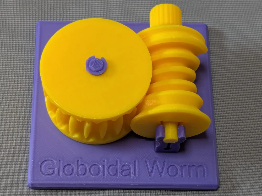
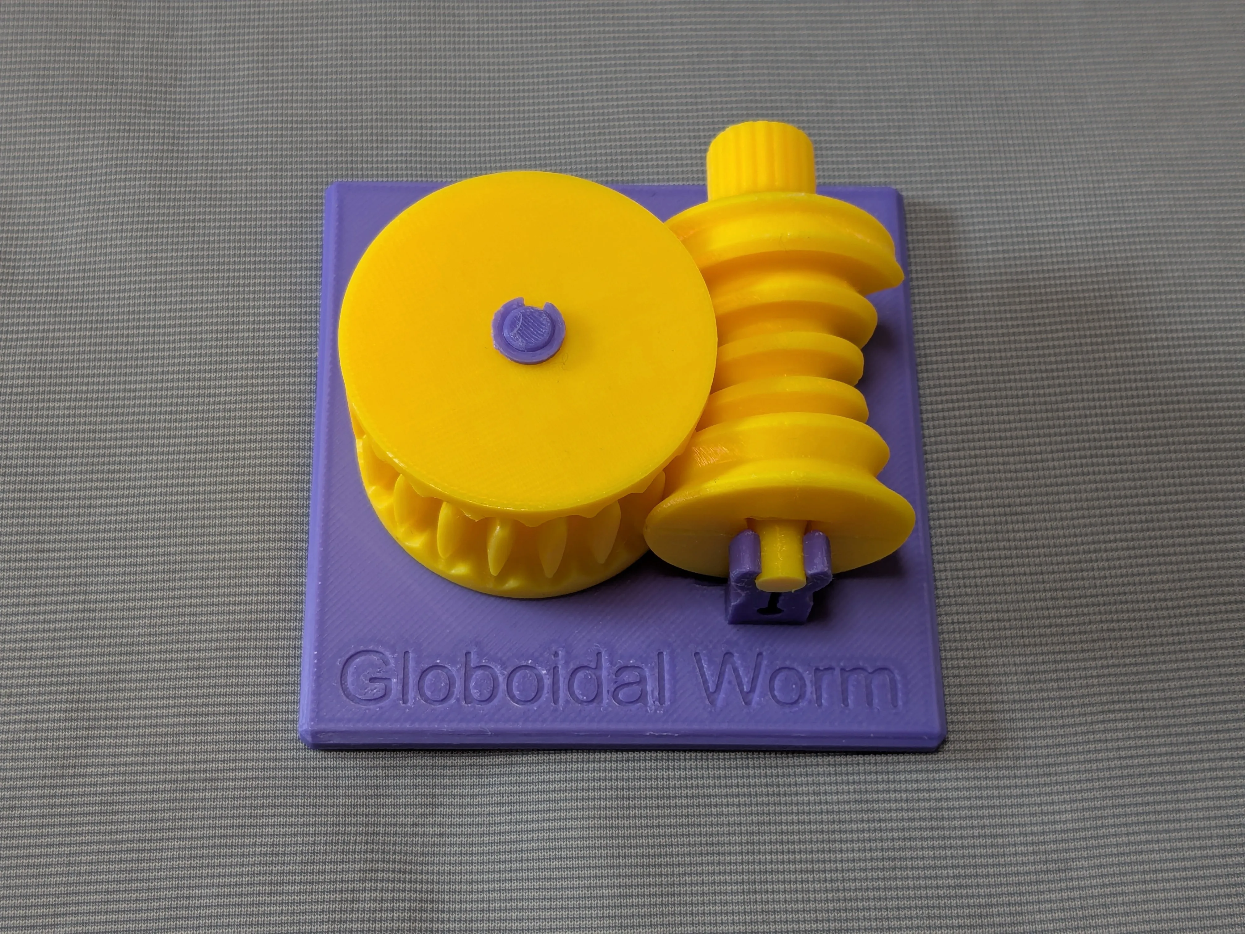
This is an educational model of a globoidal worm gear and mating worm wheel.
Brief Description
A conventional worm can be regarded as a rack helically wrapped around a cylinder. The pitch surfaces of the worm and the worm wheel are both cylindrical, so they are tangent at only one point. As one moves away from that point along the worm axis, the meshing becomes shallower, and when the wheel diameter is small, only a limited number of teeth tend to share the load.
A globoidal worm, also called a double-enveloping worm gear, has a worm surface curved to conform more closely to the wheel. This makes it possible for more teeth to participate in transmitting force at the same time.
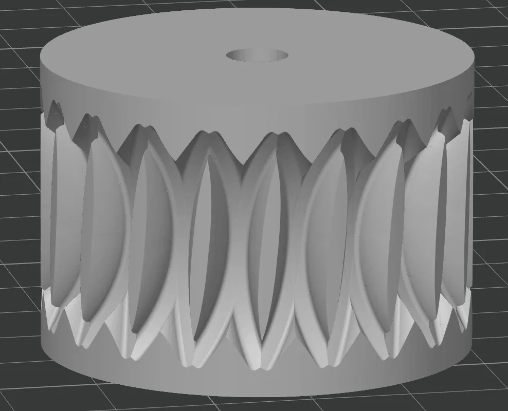
This model should be viewed mainly as a theoretical design example, not as an optimized practical design. In this example, the globoidal worm was formed by helically wrapping an involute internal-gear profile, having the same radius as the worm wheel, around a cylinder. The mating wheel was then obtained by numerically cutting a cylindrical blank with an extended version of that worm.
In the plane perpendicular to the wheel axis and containing the worm axis, the sectional profiles of the worm and wheel coincide exactly, except for backlash clearance. However, this contact is limited within that plane. Away from it, the tooth surfaces separate, so those regions do not contribute to power transmission.
This is quite different from a conventional cylindrical worm gear, where the contact line tends to extend across the full face width of the wheel. Here, the contact line extends in a direction that is essentially perpendicular.
For this reason, the globoidal worms of this type are especially advantageous when the wheel diameter is small and the wheel is thin, because the load can be distributed over a larger number of teeth. In general, globoidal worms are used where high reduction ratio and high torque capacity are required in a compact space, especially in heavy-duty reducers, indexing mechanisms, and machine-tool drives.
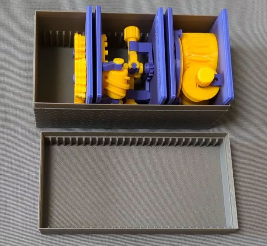
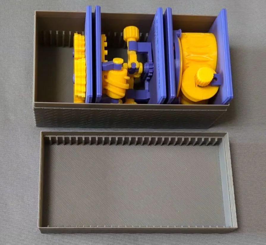
Case
This model is compatible with the case included in my first set.
Printing
- Use the models named ???-printable.stl for printing.
The models named ???-assembled.stl are provided just to show how they should be assembled.
- Use well-dried PETG to have better dimensional accuracy.
- Use 0.1 mm or 0.08 mm layer height to have smoother surfaces.
- Use slow printing speed for overhangs.
- Select “Random” seam position to have smoother rotation.
Randomly distributed seam should be easily worn out after some wearing.Printing
Sanding and Filing
Note that, in this model, the rotation of the bases for bearings is intentionally made not too smooth.
Sometimes, the gears suffer from the stringing effect and/or elephant foot effect, resulting in a too tight fit to the shafts (they are designed with a 0.15 mm radial clearance).
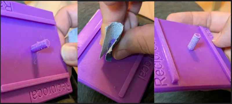
If you see rough surface on the shafts due to stringing, sand off the roughness with a small piece of sand paper.
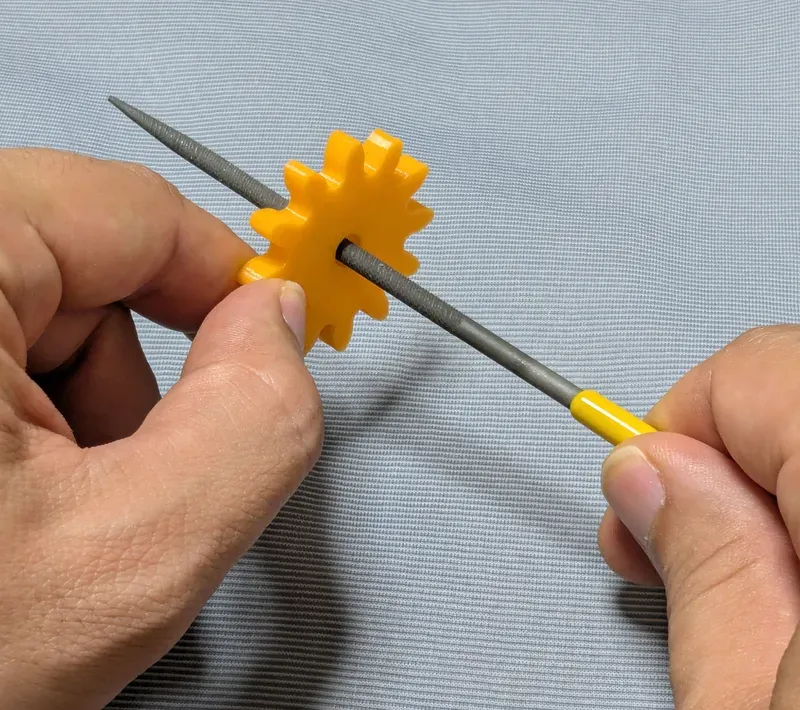
If you feel the gears do not rotate smoothly due to an elephant effect, widen the hole slightly by using a thin round bar file.
Without those issues, the parts should rotate very smoothly with minimal friction.
Assembly
Before assembly, check the tooth surface carefully to find no stringing or rough edge remaining.
If you find any, file off them before proceeding.
The worm wheel is split into two halves for easy printing with quality.
So, first, align the halves using the small dowel pins and fit them together around the worm.
Then insert the shaft through the center to secure the assembled wheel.
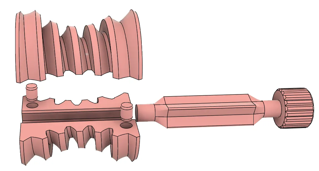
In this model, the worm and wheel correspond in section to an internal gear pair of the same diameter. This means that, if the worm is assembled first, the wheel cannot be meshed with it directly. It has to be pressed into place by taking advantage of the elastic flexibility of the plastic parts. By aligning the point where the worm thread is interrupted and applying force carefully, the wheel can be snapped into mesh.
If that is difficult, a simpler method is to mesh one wheel half with the worm first, as if screwing it into place, and then assemble the rest of the worm afterward.
Finally, place the worm and wheel set on the base plate and secure the wheel with the retention ring.
Other examples
You may also be interested in the models in my educational mechanical mechanism examples.
Find them in this collection:
https://makerworld.com/collections/15048577-my-educational-mechanism-models
Happy printing!
Acknowledgement
I got into gears thanks to K.$uzuki's amazing articles and YouTube videos. Many of the mechanisms shown in this series came from the introductions on his website. He also makes excellent gear models himself. This series wouldn’t have existed without his inspiration.
I learned a lot about technical detail of designing gear tooth profiles from Haguruma-No-Hanashi website. I’m truly grateful for that.
License (2026-03-13 updated)
- The 3D model(s) are licensed under Creative Commons Attribution 4.0 International. (unchanged)
- However, the text and images on this page are copyright reserved. (added on 2026-03-13)
License



Comment & Rating (2)