


Print Profile(9)


Description
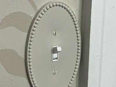
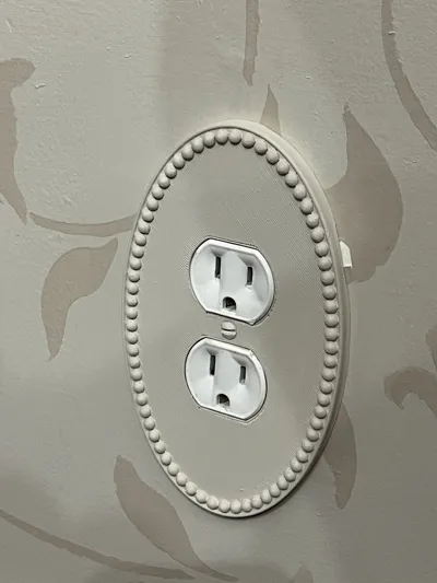
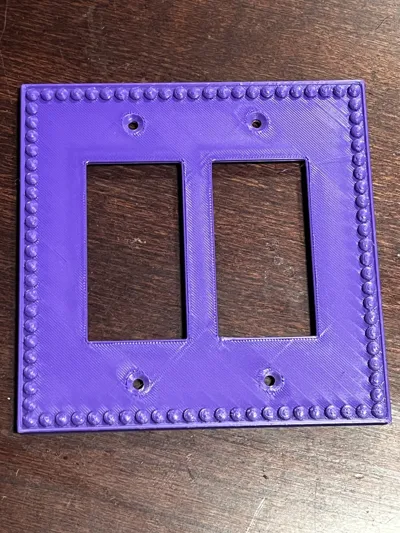
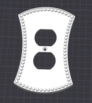
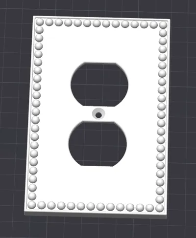
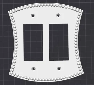
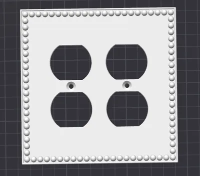
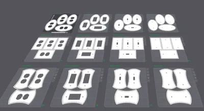
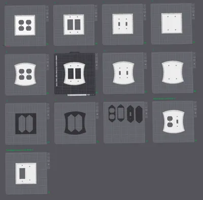
These decorative wall plates can dress up your outlets and light switches. I designed these as an homage to classic beaded wall plates that you can occasionally still find in historic homes. Included, you will find 3 main shapes: oval, rectangle, and flared. Oval plates are only available in 1-Gang plates. Rectangle and flared plates are available in 1- to 4-Gang plates. All plates follow the North American standard for box, device, and strap mounts.
All plate shapes and sizes are available in switches, duplex, decorator, and blank. These projects include templates to allow you to customize these wall plates for situations where you have mismatched devices (such as a toggle switch, a duplex outlet, and a decorator all in the same gang box). Detailed instructions on how to customize these are available below or as a separate download in the documentation section.
Disclaimer
Warning! There is a risk of electrical fire or electro-static discharge (ESD) in electrical boxes. To protect from electrical fire, electrical box coverings should be made from fire-retardant material. To protect from ESD, electrical box coverings should be should be made from ESD-safe material. In the United States, electrical box coverings must be UL certified.
These designs have not been reviewed by a qualified electrical engineer. The designer offers no warranty, either express or implied, regarding the safety or suitability of these designs for any use.
If you install these coverings, you will be installing non-UL certified coverings. Doing so may expose you to risk of electrical fire or electric shock. In the event of fire, the presence of non-UL certified coverings may void your insurance policy. Do not install these wall plates unless you understand and accept these risks.
Risks can be reduced by using a UL-rated filament (such as Prusament PETG V0) or an ESD-safe filament, but even if the filament is UL-rated, neither these designs nor your prints are UL-certified, so the above risks still apply.
Print Settings
Top and Bottom Shell Layers
The included print profiles include recommended settings for printing these plates. Specifically, they have 4 bottom shell layers and 8 top shell layers at a 0.2mm layer height, which results in a completely solid infill for the main plate surface. For me, this improved the top surface quality. Feel free to experiment with reducing the number of layers and and seeing if you get acceptable results with some sparse infill.
Supports
Unfortunately, the geometry of these prints demands heavy use of supports. You may be able to minimize supports by printing in an upright orientation, but this may affect surface quality and part strength. Given the flat nature of the underside of the plate, this project is ideal for printing in PLA with PETG support interfaces (see this article on the Bambu Wiki describing how and why to do this), since there are only 2 layers where supports contact the work piece, so filament changes are minimal. While this is not necessary, it makes these supports much easier to remove.
Note: I have experimented with using manual support painting to add a few parallel lines of supports and allowing the printer to bridge the underside of the plate, since it will not be seen. The result was that it took many layers to overcome the issues introduced by the sagging bridges. If you have your bridging dialed in better than I did, this may be a way you could save time and filament.
Customization
For multi-gang plates, you may sometimes need mismatched components, such as a mixture of decorators, duplexes, and switches in a specific configuration. Rather than attempting to model each such combination, the 2-, 3- and 4-gang profiles include non-printable templates that can be combined to make your own custom plate using only Bambu Studio. Below is a step-by-step guide to accomplish this.
Step 1: Copy the desired templates to a new build plate.
Copy the desired plate template and whatever middle templates you want to a new build plate.
Step 2: Make the template pieces printable
Select the templates, right-click, and click “Printable”.
Step 3: Merge the templates into a single assembly
Select the template pieces, right-click, and click “Merge”
Step 4: Assemble the templates
Select the assembly from step 3, and in the toolbar, select the “Assemble” tool.
Change the mode to “Point and point assembly”
Hover the cursor over the plate template. A sphere should appear representing the fixed point selection for the assembly operation. It should automatically snap to corners. On the top face of the plate template, hover over the upper-right corner of one of the empty spaces on the plate template. When the sphere snaps to the corner, left click to select it.
Once you select the fixed point, Bambu Lab will switch so the cursor displays a differently-colored sphere when you hover over the middle templates. Move the sphere to the upper-right corner of the middle template corresponding to the space you selected above.
This will result in an assembly where none of the parts moved, but the assembly dialog will list X,Y and Z offsets representing the disatance between the two selected points.
Set all three of these offsets to 0.
Once this is done, the middle template should be in the correct position relative to the plate template.
Repeat the process for each slot in the plate template. This should result in a customized plate with all templates in the correct positions.
Step 5: Combine the template bodies
With the template bodies all in the correct position, you can now combine them into a single body. Select the assembly, then click the “Mesh Boolean” tool. Ensure the dialog is in the “Union” tab. Click “Execute”. This will join all of the bodies into a single body.
At this point, slice the plate and look at the resulting preview. Ensure the slicer did not generate walls between the template pieces . The plate should appear to be a single solid. If you encounter this, return to the “Prepare” tab of Bambu Studio, right-click on the plate model, and click “Simplify Model”. Experiment with the value in this dialog. The more you simplify, the lower-quality your resulting part will be. Select a detail le vel (I recommend starting with the default) click “Apply”. Re-slice the plate and check again for the walls between template pieces. If the walls are no longer there, the operation succeeded. Either leave it like that, or undo and retry “Simplify Model” with a higher detail level . If, however, the initial attempt failed, undo and retry “Simplify Model:” with a lower detail level. Repeat this process until you are satisfied with the result.
Step 6: Apply Adaptive Layer Height
The spheres around the border of the border of the plate print at much higher quality if Adaptive Variable Layer Height is used,. Select the model, and click on the “Variable Layer Height” tool in the toolbar. Click the “Adaptive” button.
Step 7: Happy Printing!
Congratulations. You now have a custom version of this decorative wall plate for your very specific use-case. Enjoy!
Documentation (1)
License
You may create derivative works based on this object, provided that all such derivative works are published exclusively on the MakerWorld platform and include proper attribution to the original creator. You may not share, upload, host, distribute, or publish this object—or any derivative work of this object—on any other digital platform, marketplace, or distribution channel. Commercial use of this object and any derivative works is strictly prohibited. This includes, but is not limited to, selling, renting, sublicensing, or using the object in any context in which you receive monetary compensation or other financial benefits.
Comment & Rating (1)