SVEN - Desktop Robot Arm


Print Profile(3)
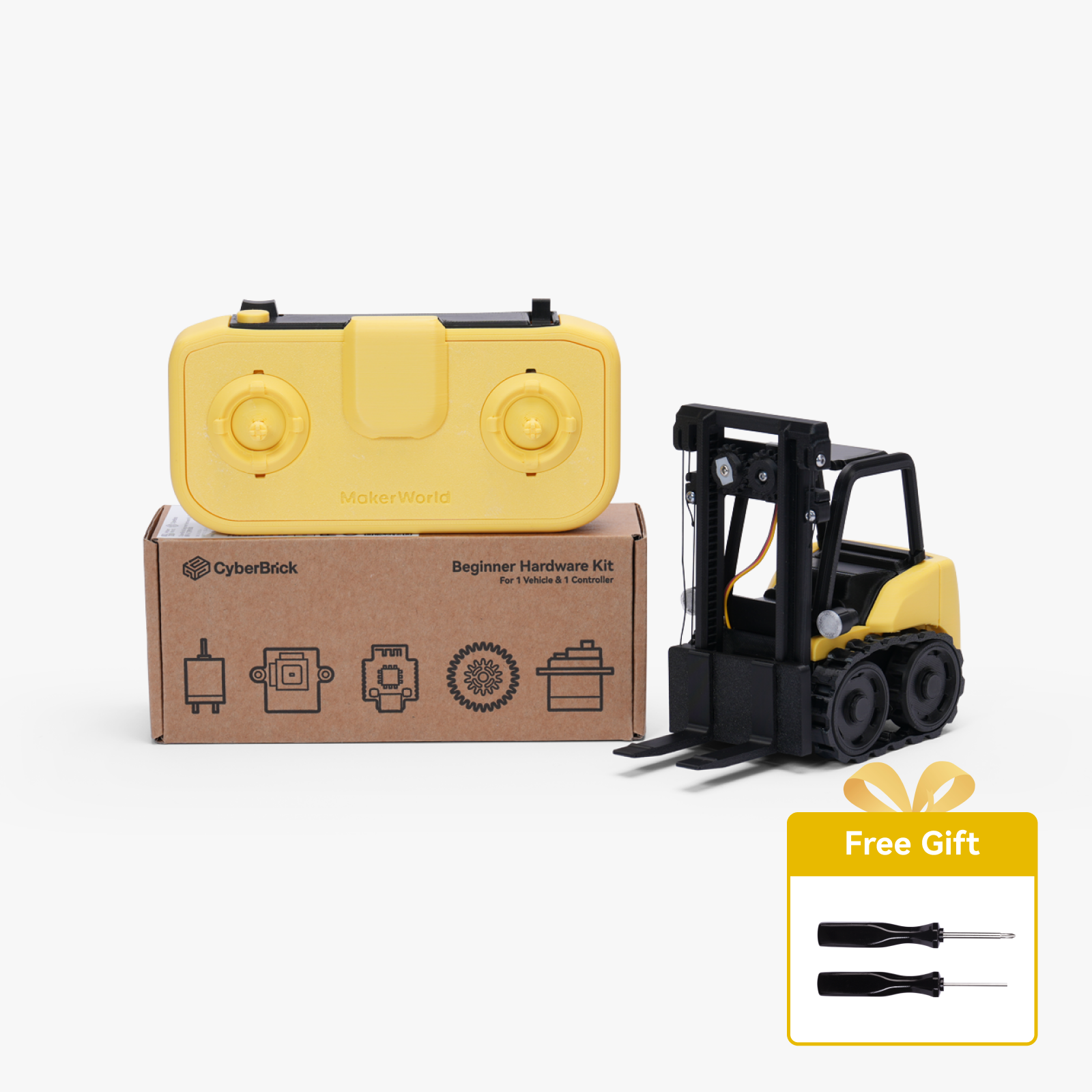
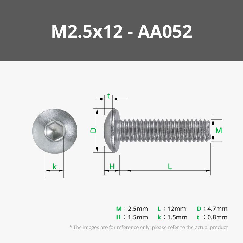
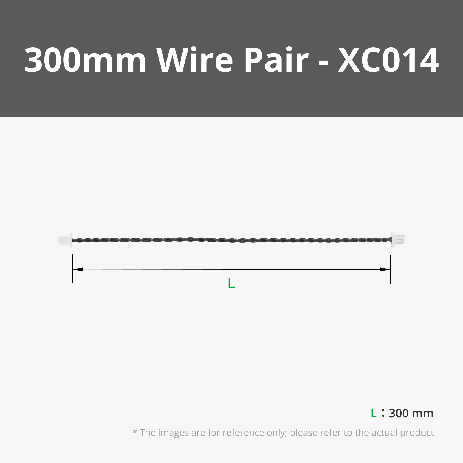
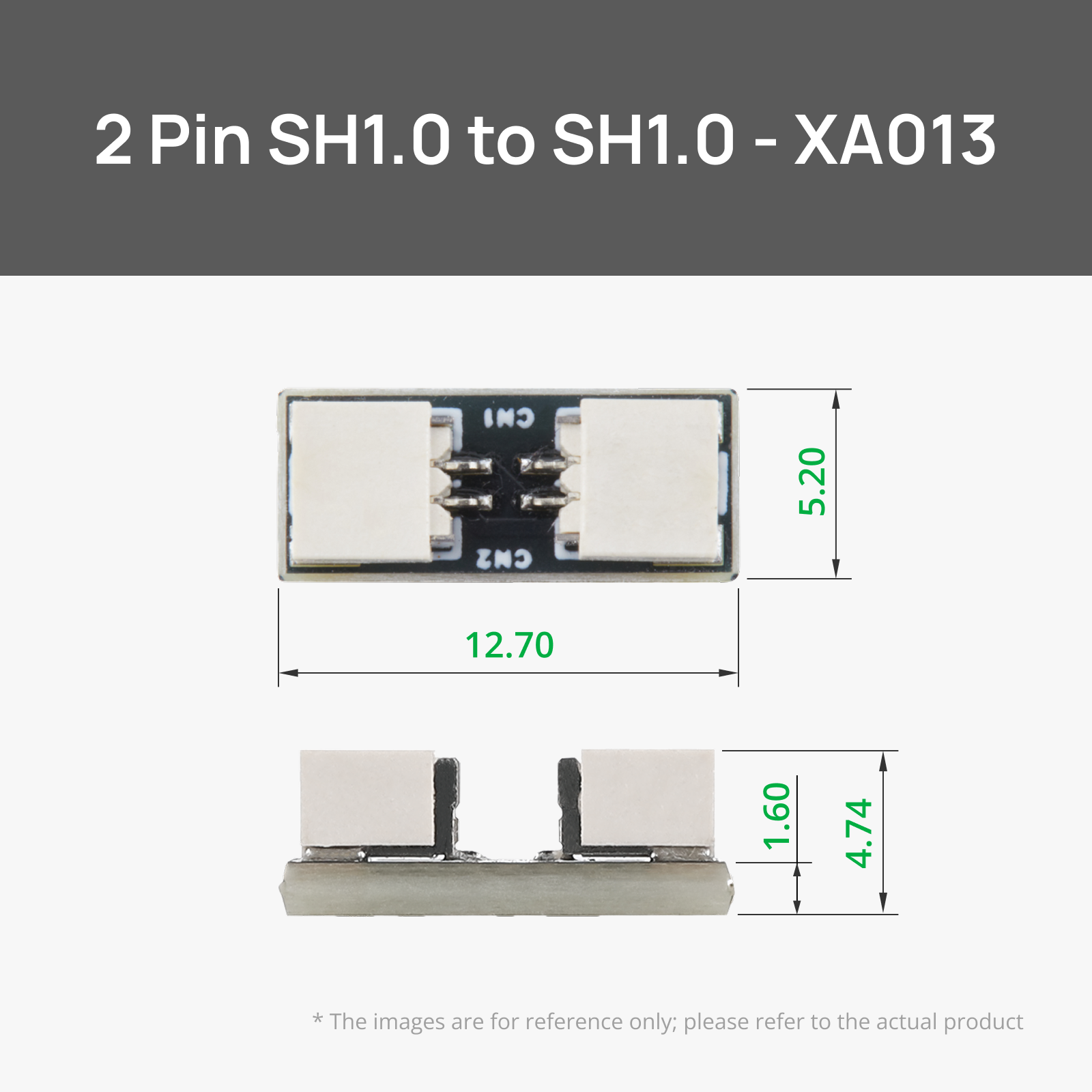
Bill of Materials


- Lubricating Grease x 1:
Description
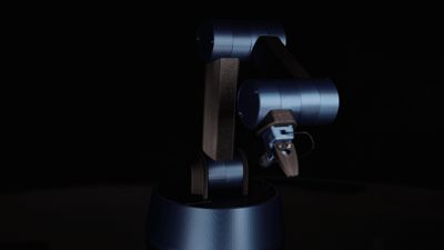
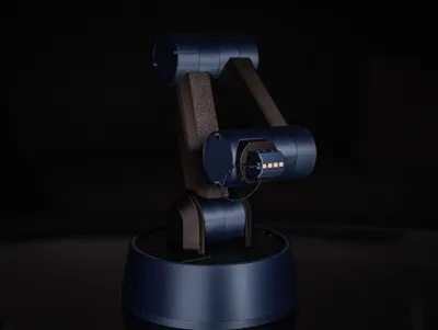
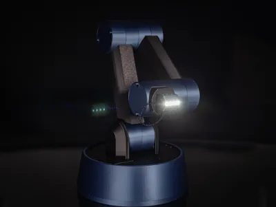
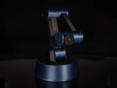
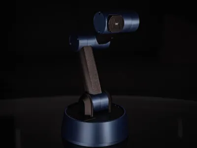
Meet SVEN - the Desktop Robot Arm
My most advanced model to date.
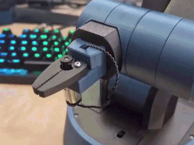
Hotswapable tool heads.
Strong axle joints capeable of providing a theoretical 18kgf/cm.
Fully designed with Maker's Supply items and Cyberbrick in mind.
This has been a passion project of mine for over a month now. While going through numerous itterations, I have learnt incredibly much regarding gears, forces and materials. All to bring you SVEN.
I am still not completely finished with this model however. I have plans to add more toolheads, as well as a custom controller in the future. Keep an eye out for updates on this!
This is a highly advanced print and building project. It requires being able to print in materials such as TPU and PA6/12, along with being able to handle low tolerances. The assembly is built up of 65 steps that can be seen in the assembly instructions added below.
The only item needed outside of what's listed in the bill of material is lubricating grease.
The Bill of Materials includes the parts needed for both toolheads.
The Robot Arm profile includes all the parts needed to print the robot arm. All duplicated parts are already in the correct amount.
Both toolheads are in their own separate profiles.
Estimated print time: 44 hours
Estimated assembly time: 2-3 hours
Most parts can be printed with normal settings. I have however reduced the printspeed in my profiles to max 150mm/s to ensure a good surface quality.
The only parts that must be printed in specific settings are the worm gears. These MUST be printed with a layer height of 0,08mm on a 0,4mm nozzle, along with a very slow speed. I have also found that printing all 8 worm gears together provides enough cooling on the parts to give a better print quality. All of this is included in the print profile.
Be careful to not force the arm segments to move by hand, as this can damage the gears!
This model is currently using the Cyberbrick Standard Remote control layout, but there are plans to design a custom controller for this. These are the controls:


Boost Me (for free)
This design was made possible by the points and boosts gathered by my earlier designs. Boosting this model will help me create even more new designs!
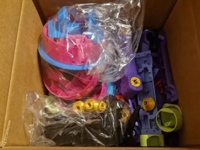
Are you in need of a storage solution for both filaments, Maker's Supply parts, AND your tools? Look no further.

Documentation (1)

License
You shall not share, sub-license, sell, rent, host, transfer, or distribute in any way the digital or 3D printed versions of this object, nor any other derivative work of this object in its digital or physical format (including - but not limited to - remixes of this object, and hosting on other digital platforms). The objects may not be used without permission in any way whatsoever in which you charge money, or collect fees.
Comment & Rating (43)