OpenGrid / Multiboard Keyhole Adaptor Plate


Print Profile(1)
Bill of Materials


Description
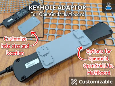
Hang devices as intended. Customize your keyhole mount adaptor for OpenGrid or Multiboard.
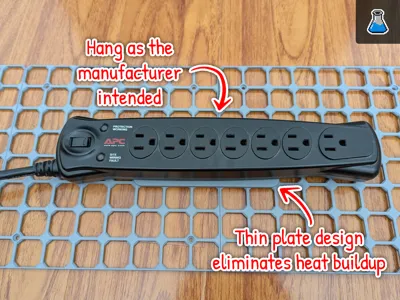
I designed this model to solve a common frustration with mounting hardware like power bars, switches, and routers to modular wall systems. Most existing solutions use "captive shells" or bulky enclosures that trap heat and force devices into awkward positions. I wanted a way to hang devices exactly as the manufacturer intended while utilizing the versatility of OpenGrid and Multiboard.
By using a thin-plate design, this adapter ensures your electronics have optimal air circulation for cooling, preventing the thermal buildup often seen in enclosed mounting options.
⚠️ Important: This model must be opened in MakerWorld to be customized. Customization is not compatible with Handy App or Bambu Studio at this time. https://makerworld.com/en/models/2484153-opengrid-multiboard-keyhole-adaptor-plate#profileId-2728747
Features
- Dual-System Compatibility: Native push-fit support for OpenGrid and Multiboard organizational systems.
- Fully Parametric Design: Utilizes OpenSCAD to allow users to generate custom plates by adjusting hole sizes and locations to fit any specific device.
- Hardware-Optimized Hanging: Enables mounting of power bars, routers, and switches exactly as the manufacturer intended using their original keyhole slots.
- Advanced Thermal Management: The thin-plate geometry promotes superior air circulation and cooling compared to restrictive, heat-trapping captive-shelled designs.
- Universal Hardware Support: Specifically designed to incorporate self-tapping screws for a secure, custom-fit mounting interface.
Specifications
- Compatible systems: OpenGrid, OpenGrid Lite, MultiBoard
- Customizable plate size
- Customizable screw location
- Screw Compatibility: M3 (customizable)
- Plate Thickness: 2mm (customizable)
Support Me!
Boost Me (for free)
If you enjoy this design please give me a Boost if you can!
Customization and Printing Guide
- Go to the MakerWorld and find the model.
https://makerworld.com/en/models/2484153-opengrid-multiboard-keyhole-adaptor-plate#profileId-2728747 Select “Customize”.

When present with the pop-up, select the model and select “Customize”.

Customize the design using the parameters on the bottom left. Press the “Generate” button to preview your design.

- Once you are happy with the design select Download on the top right corner and download the design as a .3mf file. 5. Open the .3mf file in Bambu Studio.
Suggested Slicer Settings
- Quality > Only one wall on first layer : Selected
- Strength > Wall loops: 4
- Strength > Bottom shell layers: 4
- Strength > Sparse infill pattern: Rectilinear
Credits / Licensing
- Design by PixelFanLabs – With a curious mind, integrity, and your hands in the soil, you can create anything.
- Attribution: A special thank you to the designers who pioneered these organizational standards. This model was design to work with these ecosystems:
- OpenGrid: This model is compatible with the OpenGrid standard by Dave (Dave's Creative Workshop)
- Multiboard: This model is compatible with the Multiboard system by Jonathan (Keep Making).
- License – All Rights Reserved
- Personal Use Only: You may print this for your own use.
- No Redistribution: Do not re-upload or distribute these digital files on any other platform.
- No Derivatives: Modification of this design—including the removal of the engraved PixelFanLabs signature—is strictly prohibited.
License
You shall not share, sub-license, sell, rent, host, transfer, or distribute in any way the digital or 3D printed versions of this object, nor any other derivative work of this object in its digital or physical format (including - but not limited to - remixes of this object, and hosting on other digital platforms). The objects may not be used without permission in any way whatsoever in which you charge money, or collect fees.
Comment & Rating (15)