
Pokemon Topper for Stern Pinball


Print Profile(1)

Description
Please read carefully what else you need and how I did the wiring. If you still have questions… then this is not the right project :-) This product is a handmade unique piece (DIY). Use at your own risk. I assume no liability for damages, injuries, or consequential damages resulting from the use, improper handling, or faulty function of the product. The user is responsible for checking the safety and functionality before use.
All information is without guarantee.
Acknowledgments: a fantastic creation by yoyothechicken and here's the link to the highlight: the Pokeballs!!
You need to print all 4 Pokeballs and process them further. Drill a hole in the bottom (5mm is enough) for a 3x0.14 cable.
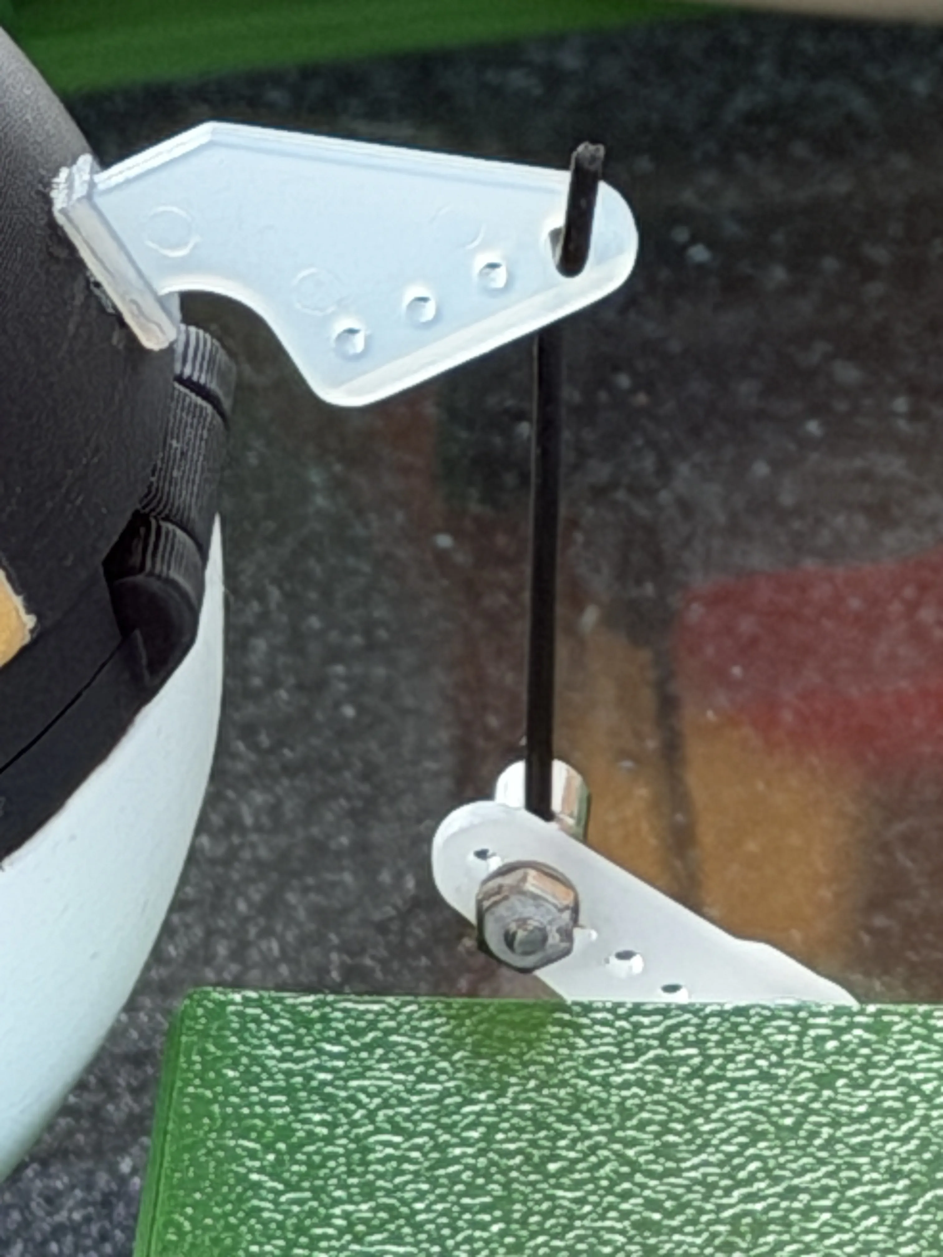
Fit the control horns into the lid and glue them firmly with superglue.
Please read carefully what else you need and how I did the wiring. If you still have questions… then this is not the right project :-)
You still need some accessories:
12V-5V voltage converter for 1x Arduino Uno R3 and LED rings
Mini Servos SG90 9G are intended as motors. These should receive a capacitor of 1000uF in the 5V connection to smooth out voltage spikes and motor "jitter". Cable 4x0.14 and 3x0.14 or similar...
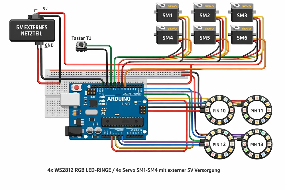
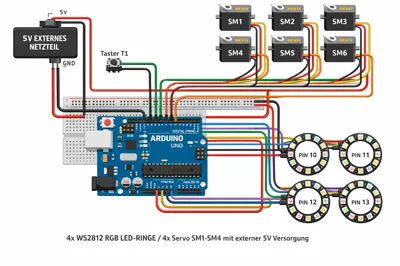
The Arduino is wired as follows:
Button to trigger animation: to Pin 2 against GND
Servo Signal Pin
SM1 3
SM2 5
SM3 6
SM4 9
Red → external 5 V
Brown/Black → GND
Signal → respective Pin
The LEDs are assigned to the outputs as follows
Each ring has:
5V
GND
DIN
Ring Data Pin
Ring1 10
Ring2 11
Ring3 12
Ring4 13
Connection per ring:
5V → external 5 V
GND → common ground
DIN → respective Pin
330 Ω resistor between Arduino Pin and DIN respectively
and one 1000 µF electrolytic capacitor between 5V and GND of the entire 5V power supply
LED Rings:
4x LED rings with 8 WS2812 5050 5 V
The signal line D1 must receive a 330 Ohm resistor from you… otherwise, you risk burning out the first LED in the ring.
For the sign and Grass LED strip:
12V LED strip RGB and 2x LED Controller RGB
For connection to the Stern Pinball powerboard (at your own risk)
Socket and crimp contacts
To control the Pokeballs, I used pre-made control horns with pushrods.
THE POKEBALLS:
a fantastic creation by yoyothechicken and here's the link to the highlight: the Pokeballs!!
Boost Me (for free)
License

You shall not share, sub-license, sell, rent, host, transfer, or distribute in any way the digital or 3D printed versions of this object, nor any other derivative work of this object in its digital or physical format (including - but not limited to - remixes of this object, and hosting on other digital platforms). The objects may not be used without permission in any way whatsoever in which you charge money, or collect fees.


Comment & Rating (2)