Search models, users, collections, and posts

Anycubic Kobra 2 neo linear rod mod - Y axis
IP Report
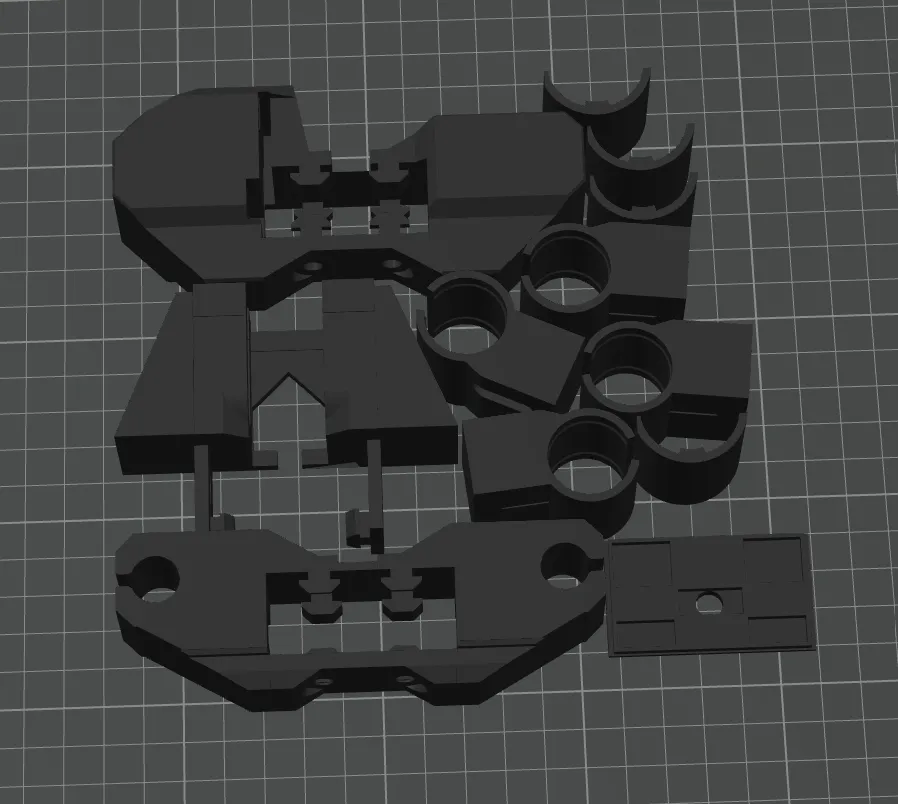
Print Profile(1)
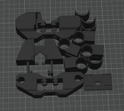
0.2mm layer, 2 walls, 15% infill
Designer
5.6 h
1 plate
Open in Bambu Studio
Boost
8
10
4
1
16
1
Released
Description
Kobra 2 Neo mods!
Materials Required
- LM12UU linear bearings — 4 pcs
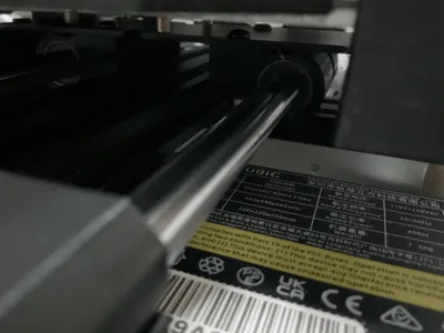
- 12 mm × 350 mm linear rods — 2 pcs
- M3 screws — 8 pcs (you could use m4 or m5 screws too, just make sure you have a t nuts for that size)
- M3 T‑nuts (for 2020 aluminum extrusion)
- Filament (ABS or PETG strongly recommended)
- Tape (optional, for rod shimming)
- Superglue (for limit switch mount)
Use heat‑resistant materials such as ABS or PETG. PLA is not recommended due to heat deformation.
🔧 Assembly Instructions
0. Preparation
- Ensure all printed parts are complete and dimensionally accurate.
- Power off and unplug the printer before starting.
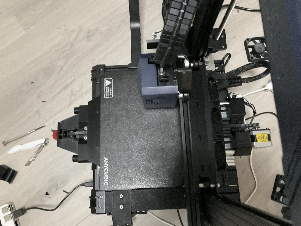
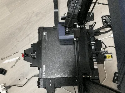
1. Remove the Heated Bed
- Unscrew and lift off the heated bed to expose the Y‑axis carriage.
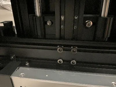
2. Remove the V‑Wheels
- Unscrew the V‑wheels from the Y‑axis bed frame.
- Keep the screws and nuts — they will be reused.
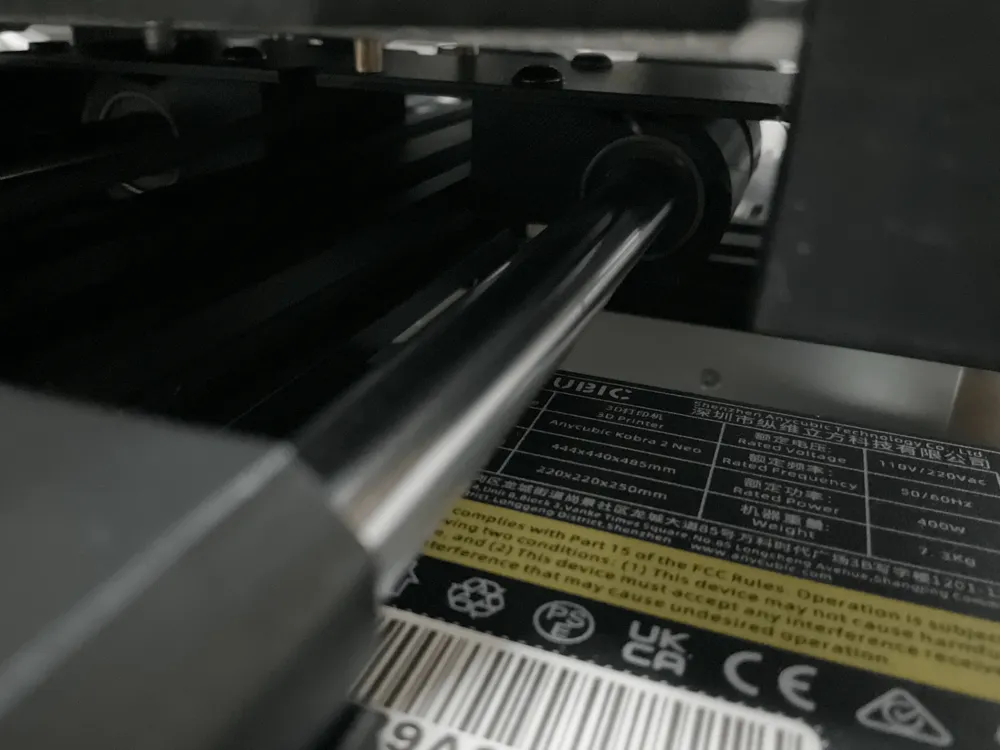
3. Install the Linear Bearings
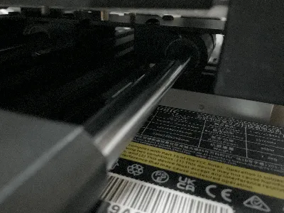
- Slide one LM12UU bearing into each printed bearing adapter.
- Ensure they are fully seated and aligned.
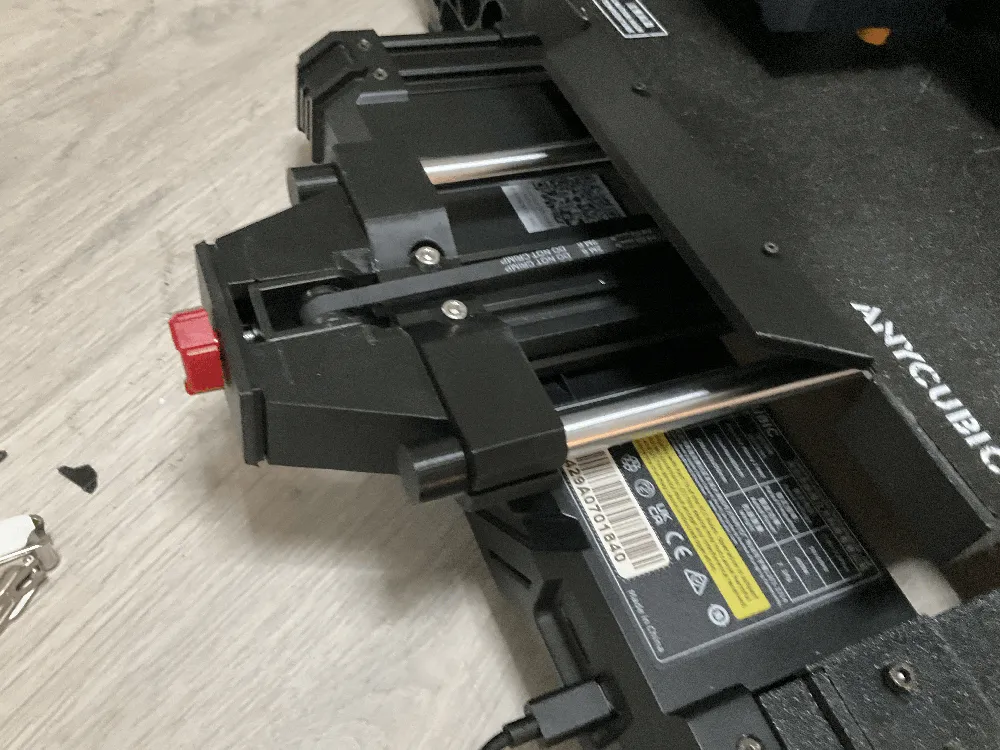
4. Mount the Bearing Adapters
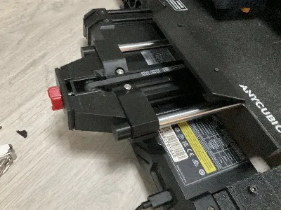
- Using the original V‑wheel screws and nuts, attach the bearing adapters to the bed frame.
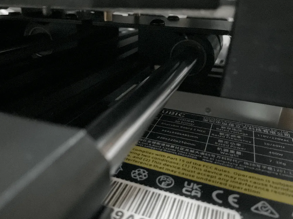
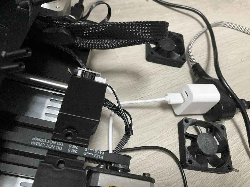
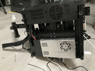
- Refer to the images for correct orientation.
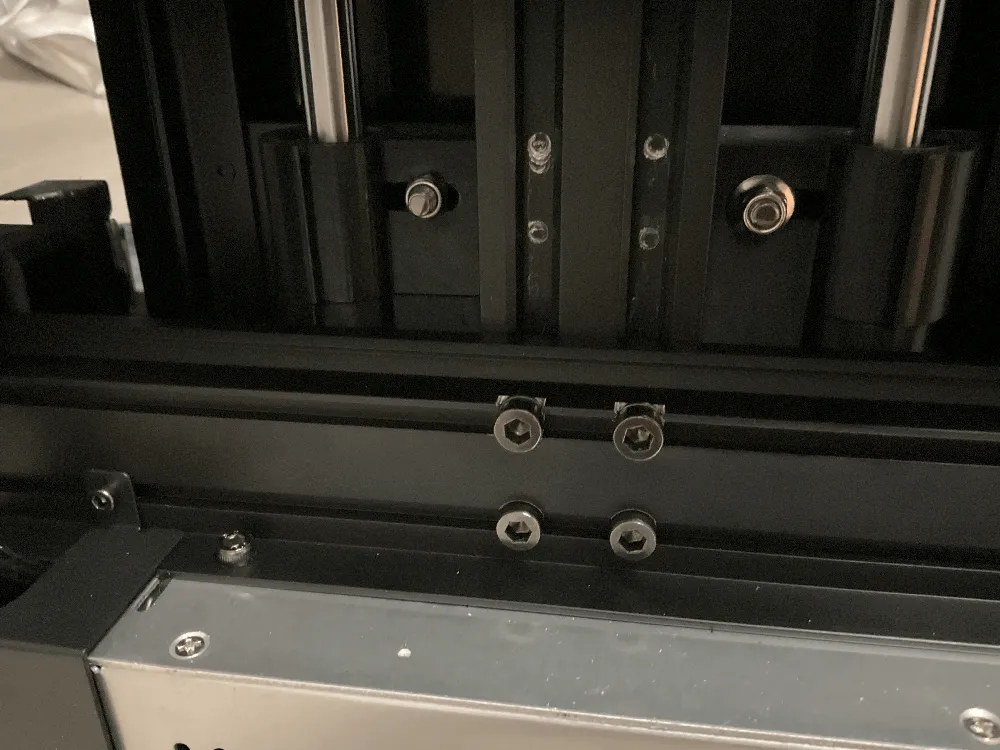
5. Remove the Y‑Axis Extrusion Screws
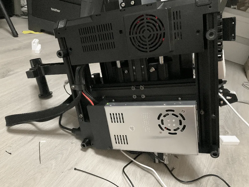
- Flip the printer over.
- Remove the four screws in the center that secure the Y‑axis aluminum extrusion to the frame.
6. Prepare the Rod Mounts
- Pre‑install M3 screws(or m4 or m5 size) and T‑nuts sideways into the:
- Linear Rod Back Mount
- Linear Rod Front Mount
- Ensure the T‑nuts can rotate and lock into the extrusion when tightened.
7. Install the Back Rod Mount
- Slide the Linear Rod Back Mount into the extrusion first.
- Push it fully to the rear.
- Tighten all M3 screws to lock the T‑nuts in place.(or m4 or m5 would work too as long as you have the t nuts)
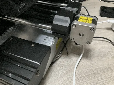
8. Install the Front Rod Mount and Belt Tensioner
- Slide the Linear Rod Front Mount into the extrusion but do not tighten yet.
- Install Belt Tensioner 1 onto the front mount.
- Slide the front mount forward to the correct position, then tighten the screws to secure it.
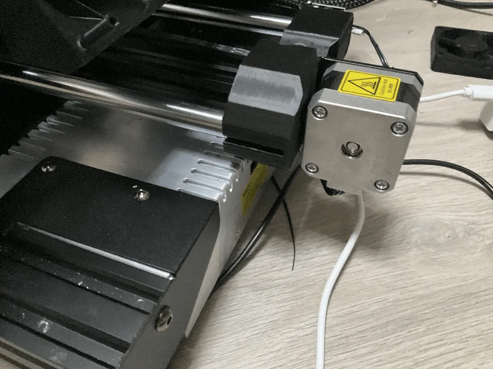
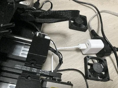
9. Install the Limit Switch Mount
- Superglue the Limit Switch Mount onto the Linear Rod Back Mount as shown in the images.
- Once cured, screw the limit switch into place.
- If the linear rods feel loose, wrap a thin layer of tape around the ends to improve fit.
License

This user content is licensed under a
Creative Commons Attribution-Noncommercial-Share Alike


Comment & Rating (4)