SATA Cartridge Bay 3.5


Print Profile(2)
Bill of Materials


- Combined SATA Adapter x 1: https://www.aliexpress.com/item/1005008747395106.html
Description
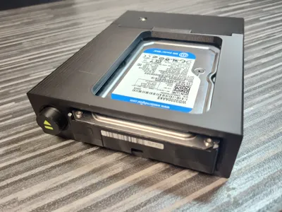
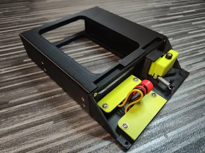
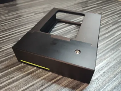
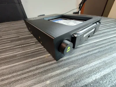
This model is a floppy-style drive bay designed for quick, tool-free insertion and removal of standard 3.5” drives up to 26 mm in height using a fully mechanical system.
The core concept is zero attachment to the drive itself — nothing is mounted, screwed, clipped, or fixed to the disk. A standard 3.5” drive is inserted directly into the bay without trays, carriers, or drive-specific hardware.
The mechanism is entirely passive and purely mechanical. No electronics, motors, or actuators are used. Insertion and ejection are achieved through a linear button rod, a pivoting lever, and a guided pusher, providing a tactile and durable physical interface.
It is well suited for retro PC builds, diagnostic setups, archival systems, and environments where frequent physical drive swapping is required.
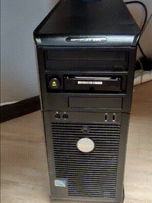
The unit mounts into a standard 5.25” optical drive bay.
This model is part of SATA Cartridge Bay series:
- SATA Cartridge Bay 2.5 Passive (without eject button)
- SATA Cartridge Bay 2.5
- SATA Cartridge Bay 3.5 (this model)
Required Materials
SATA Adapter
- 1× Combined male-female SATA data + power adapter (link)
One end plugs directly into the drive, carrying both data and power.
The opposite end provides separate SATA data and power connectors for the host system.
Recommended cable length: approximately 10 cm.
Longer cables may be used, but excess length can interfere with the internal space when closing the cover.
Threaded Inserts
- 19× M3 threaded insert nuts, maximum length 6 mm.
Standard 5.25” drive bays provide eight mounting positions (four per side).
If all eight chassis mounting points are used, 19 inserts are required in total.
If only four chassis mounting screws are used, the total required insert count is 15.
Screws
All screws are M3 with a recommended thread length of 5–7 mm.
- 8× chassis mounting screws (5.25” standard mounting positions).
Four screws are sufficient for secure mounting; eight may be used if desired.
- 4× Front Frame to Rear Housing connection.
Low-profile flat head screws are recommended to ensure proper clearance.
- 4× SATA connector mounting (two per connector).
- 2× Rear Cover mounting screws (inserted from the underside).
Head height must not exceed 2 mm. Flat head screws are recommended.
- 1× Eject Lever pivot screw (installed from above through the Rear Cover).
Head height must not exceed 2 mm.
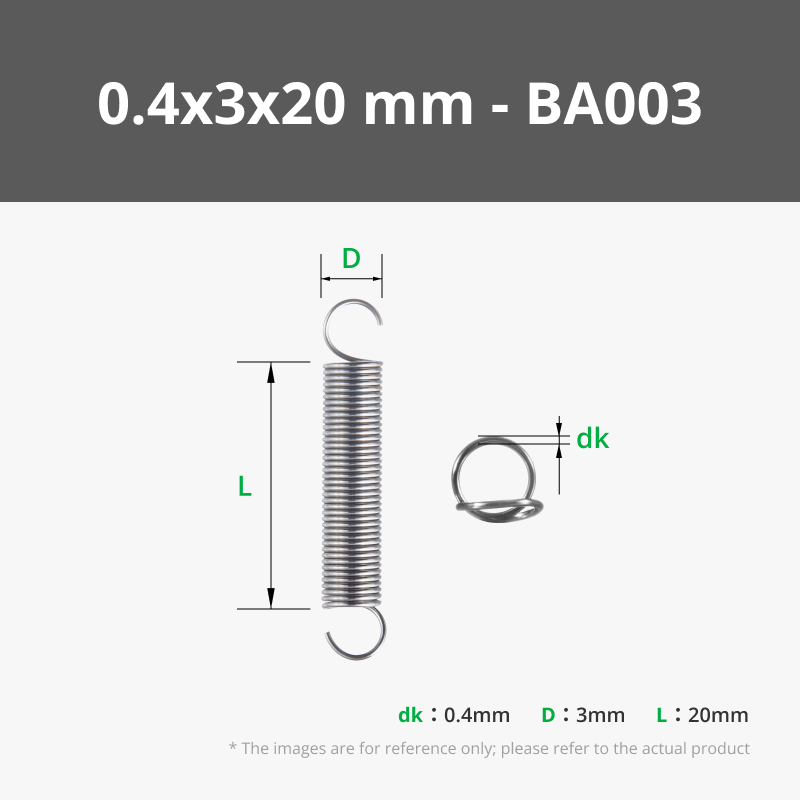
Spring
- 1× Extension (tension) spring, total length 20–26 mm, with hooks on both ends.
The device can operate without a spring; however, in that case the eject button will not automatically return and will reset only when a drive is inserted.
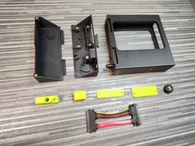
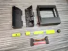
Printable Parts
Main Structure
- Front Frame
Front section where the drive is inserted. Includes the integrated linear button rod.
- Rear Housing
Primary structural body that supports the mechanical system and the SATA connectors.
Eject Mechanism
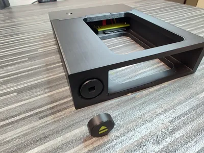
- Eject Button
External button element with a square interface that mates with the integrated button rod.
- Eject Lever
Internal pivoting element that converts linear rod motion into rotational movement.
- Disk Pusher
Linear floating element that transfers eject force directly to the drive.
Connector Components
- Drive Connector Cover
Secures the drive-side SATA connector inside the Rear Housing.
- External Connector Cover
Secures the external SATA connector and provides cable stabilization.
Enclosure
- Rear Cover
Upper structural cover that closes the assembly and reinforces the pivot area.
Assembly Steps
1. Install the Threaded Inserts
Heat-set all M3 threaded insert nuts into their designated locations in the printed parts.
Ensure each insert sits flush and properly aligned before proceeding.
2. Join the Front Frame and Rear Housing
Slide the Front Frame into the Rear Housing from the top, aligning the centered guiding slot.
Once fully seated, secure the two parts together using the four designated rear-mounted M3 screws.
Ensure proper alignment before tightening.
3. Install the SATA Connectors
Insert both SATA connectors into their designated mounting positions inside the Rear Housing.
Ensure correct orientation before fully seating them.
Secure the connectors in place using the Drive Connector Cover and the External Connector Cover.
4. Install the Disk Pusher
Insert the Disk Pusher into its dedicated guide channel inside the Rear Housing.
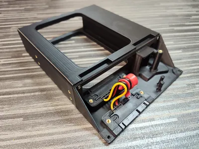
5. Install the Eject Lever
Place the Eject Lever onto its pivot cylinder inside the Rear Housing.
The lever must be oriented with the spring hook facing downward, even if no spring is used.
The Rear Housing includes two spring anchor hooks to accommodate different spring lengths (20 mm and 26 mm total length).
If using a spring, attach it between the selected housing hook and the lever hook.
6. Install the Rear Cover
Lower the Rear Cover vertically into position.
Ensure the Eject Lever pivot cylinder enters the dedicated opening in the cover.
Fasten the Eject Lever pivot cylinder from above using the designated M3 screw.
Secure the cover using the two designated M3 screws inserted from the underside.
7. Install the Eject Button
Align the square protrusion of the Eject Button with the square opening of the integrated button rod.
Press firmly until fully seated.
8. Mount the Unit into the Chassis
Insert the assembled unit into the 5.25” drive bay of the chassis.
Secure it using four or eight M3 mounting screws, depending on preference.
Troubleshooting
Button Rod Sticking
In rare cases, the integrated button rod may stick and not move freely after printing. This can occur due to filament characteristics, printer tolerances, or slight internal fusion between moving surfaces.
If the rod does not move, do not apply force from the rear side of the rod. Instead, apply controlled pressure from the button side, where the structure is better reinforced. Applying force from the rear may cause the rod to break.
After the initial release, the mechanism should operate normally.
Material behavior may vary. The design has been tested using BambuLab PLA Basic on a BambuLab P1S with the default filament profile, where the rod released easily if slight sticking occurred.
Supporting the Drive During Ejection
When pressing the eject button, it is recommended to support the drive with your hand as it is released.
This is especially important when using mechanical hard drives (HDD), as their weight may cause them to drop out of the bay once fully disengaged.
License
You may create derivative works based on this object, provided that all such derivative works are published exclusively on the MakerWorld platform and include proper attribution to the original creator. You may not share, upload, host, distribute, or publish this object—or any derivative work of this object—on any other digital platform, marketplace, or distribution channel. Commercial use of this object and any derivative works is strictly prohibited. This includes, but is not limited to, selling, renting, sublicensing, or using the object in any context in which you receive monetary compensation or other financial benefits.
Comment & Rating (3)