ESP32-C3 Telemetry Node Housing SHT31 Sensor


Print Profile(1)
Description
Project Description
This enclosure was developed for a modular embedded telemetry node.
The focus is clearly on function, measurement stability, and reproducible manufacturing.
Development Goals:
- Compact design
- Clean internal structure
- Thermal decoupling of sensor and electronics
- Good air circulation at the sensor
- Printing with support
- Quick assembly
The model is not a decorative object but a practical electronics enclosure for real projects.
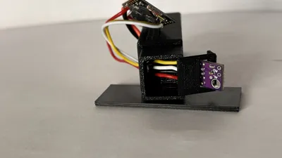
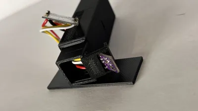
Internal Enclosure Structure
The enclosure consists of two separate areas:
Electronics Area
- ESP32-C3 Super Mini
- Power connection
Sensor Area
- SHT31 Temperature and Humidity Sensor
Both areas are separated by an internal partition wall.
This partition wall contains a dedicated cable feed-through.
This design serves for thermal decoupling and reduces the influence of the ESP32's self-heating on the sensor's readings.
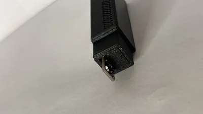
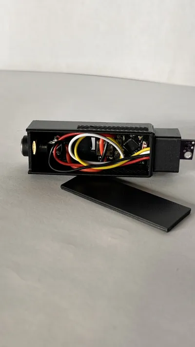
Heat Dissipation Regulation
For temperature stabilization, the enclosure has integrated air vents, as visible in the pictures.
These ensure:
- Dissipation of ESP heat
- Air exchange in the sensor area
- More stable temperature and humidity measurements
The airflow design is intentionally functional, not decorative.
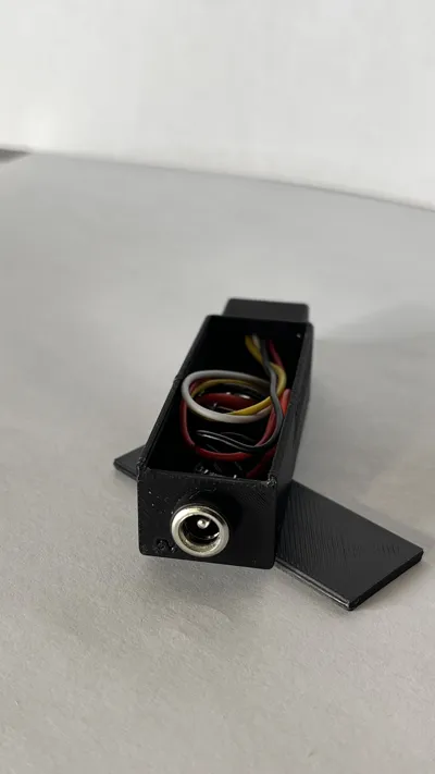
Wiring Overview
Power Supply
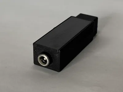
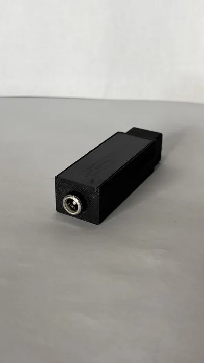
Connection via standard DC barrel connector:
- Outer diameter: 5.5 mm
- Inner diameter: 2.1 mm
- Type: DC Barrel Jack
- Common polarity: inner positive (+), outer ground (−)
(Check polarity before connecting)
Recommended supply:
- 5V via 5V pin
or - 3.3V via 3V3 pin (only with a stable regulated power source)
Sensor Wiring (SHT31 via I²C)
- VCC → 3V3
- GND → GND
- SDA → selectable GPIO
- SCL → selectable GPIO
Most SHT31 modules have integrated pull-up resistors.
⚠ Assembly Note
Due to the narrow cable feed-through in the partition wall, the following should be observed during assembly:
Generally, it is recommended to:
- Thread the sensor cable through the feed-through first
- Then solder it to the ESP32
Alternatively, it is possible to solder the cables first and then carefully route them through – depending on cable length and connectors.
The feed-through is deliberately kept compact to prevent unnecessary air mixing between the electronics and sensor areas.
Note
This enclosure is aimed at developers and makers with basic soldering skills.
Electrical safety and correct power supply must be ensured independently.
Lid System
The enclosure is closed via an integrated rail system.
The lid is guided in and fits precisely into the enclosure.
Advantages:
- No screws required
- Clean aesthetics
- Quick access to electronics
- Repeatedly openable and closable
The system is designed for functional stability and everyday usability.
Recommended Print Settings
- Layer height: 0.2 mm
- Wall lines: 3–4
- Infill: 15–20% (Gyroid or Grid)
- Nozzle: 0.4 mm
- Material: PLA or PETG
The model is designed to be reliably printed without support structures.
NorthForge3D
Functional 3D designs for embedded systems, electronics, and practical maker projects.
Developed with system. Built for deployment.
License
You shall not share, sub-license, sell, rent, host, transfer, or distribute in any way the digital or 3D printed versions of this object, nor any other derivative work of this object in its digital or physical format (including - but not limited to - remixes of this object, and hosting on other digital platforms). The objects may not be used without permission in any way whatsoever in which you charge money, or collect fees.
Comment & Rating (0)